This thread has been locked.

If you have a related question, please click the "Ask a related question" button in the top right corner. The newly created question will be automatically linked to this question.

DCA1000EVM: Some questions regarding raw data and angle estimation algorithm

Part Number: DCA1000EVM

Hello,

I have some questions regarding raw data collection on DCA1000EVM and angle estimation algorithm.

1) DCA1000EVM can collect raw data in complex format. How does the device collect data in complex format? As far as I know the antenna can only sense signal magnitude or intensity, how does it get signal phase information?

2) In angle FFT algorithm, if I use 2 Tx and 4 Rx, 8 virtual antennas in total, is it true that I can only get 8 possible angle values based on angle-FFT? From the visualizer I can see that there are far more than 8 possible angle values. Can I have more explanation on the angle-FFT algorithm? And why don't we just solve a equation set of 8 virtual antennas to estimate omega and use omega to calculate angle?

3) Why does angle FFT take the output of 2D FFT? I can understand that the phase change of 1D FFT peaks could be used to estimate small distance change to the object. I would have no doubts if angle-FFT takes the output of range FFT. Why does angle FFT take 2D FFT outputs? Is there any physical insights behind 2D FFT result?

Thank you very much!

Best Regards,

PJ

  • Hi,

    It seems that you have general questions about radar signal processing.

    I encourage you to view our training series: introduction to mmwave sensing

    training.ti.com/mmwave-training-series

    After viewing this, please also review the mmWave SDK demo documentation. It provides a detailed overview on how a generic radar signal processing algorithm is implemented.

    file:///C:/ti/mmwave_sdk_02_01_00_04/packages/ti/demo/xwr16xx/mmw/docs/doxygen/html/index.html

    Thank you

    Cesar

  • Dear Cesar,

    Thanks for replying.

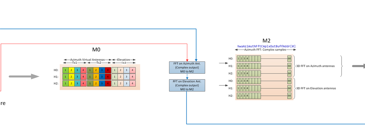
    I have watched the training series. In the AoA document, for azimuth FFT, it looks like

    There are 12 virtual antennas in total, and for Tx1 and Tx2 there could be 8 virtual antennas to perform azimuth FFT. I was wondering how come that the number of complex samples is 64 after the azimuth FFT? and also for Elevation Ant. why the number of complex samples is also 64? Could you please tell me the detailed implementation of this part?

    Thank you very much!

    Best Regards,

    Peijun Zhao

  • Because angle inputs are very few (8/12 for Ntx = 2/3), it results in poor accuracy of estimation if you try to do a smaller FFT, a bigger FFT basically interpolates with zero padding. The resolution - smallest angle separation between two objects simultaneously present in the seen to be able to see two distinct peaks in the spectrum is still determined by the number of virtual antennas in the case of this algorithm for angle estimation  and is 2/Nvirtual radians i.e you cannot improve resolution by doing a bigger FFT but you can improve accuracy. You can also use other interpolation methods but FFTs are cheaper in HWA/DSP. Accuracy will ultimately be limited by SNR.

    Regarding question 3), in general angle FFT can be done post 1D FFT as the angle is along the spatial dimension [Rx-es], not the slow time (doppler) dimension but for TDM-MIMO, you have to do doppler compensation before you do angle FFT on the virtual antennas and to do doppler compensation you have to do doppler estimation i.e doppler FFT first. Also, in our processing chain, we do CFAR on range-doppler and perform angle computation only on the points detected by the CFAR.

  • Dear Piyush,

    Just one more quick question. Since the angle estimation accuracy would increase if we do zero padding on angle FFT, is this the same with range FFT and doppler FFT? Will range FFT and Doppler FFT produce a more accurate result if we do zero padding?

    Thank you very much!

    Best,

    PJ

  • yes, up to a limit determined by SNR.