This thread has been locked.

If you have a related question, please click the "Ask a related question" button in the top right corner. The newly created question will be automatically linked to this question.

FDC1004EVM: Differential measurements, saturation problems

Part Number: FDC1004EVM
Other Parts Discussed in Thread: FDC2114, FDC1004

Hi,

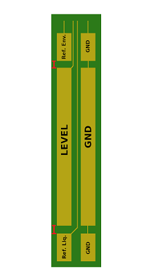
We are prototyping capacitive measurements for level measuring on a cylindrical container with a diameter of approximately 30 cm. The sensor electrodes are about 50 cm long. We have seen some promising results with single-ended measurements using copper tape. Ideally we would use differential measurements in order to filter out as much outside disturbance as possible. However, when testing differential measurements, we run into problems.

The simplest differential setup uses two electrodes, one connected to CIN1 and the other to SHLD2, and the measurement is defined as CHA = CIN1 and CHB = CIN4 (which is floating but in-phase with SHLD2, if I have understood this correctly).

The differential measurement immediately goes into saturation. Adding a large negative offset capacitance seemingly moves the measurement out of saturation again (to about 14 pF), but the measurement just stays at the same exact level and does not vary at all, so it still seems to be locked/saturated somehow. What is happening here?

Also: The FDC1004EVM has two pins for SHLD1 and two pins for SHLD2. Is it just the same which of the two pins (for the same shield) I use, or are they wired differently somehow?

  • Update: I cut the copper tape electrodes to approx. one fourth of the original width, and this removed the saturation problem. However, the sensitivity is now really, really bad. The change in measured capacitance from empty to full container could only barely be seen. Is this to be expected?

  • Hello Lars,

    SHLD1 and SHLD2 are sometimes shorted and sometimes 180 degrees out of phase. The latter is the case for differential measurements. You can read more about the two shield pins in section 8.3.1 in the datasheet. 

    In differential measurements, the CAPDAC is disabled, so you will not be able to add a capacitive offset to the measurement. Your sensors are very large, and it sounds like the differential capacitance between them is greater than 15pF. It's also possible that the input capacitance for each channel is larger than 115pF. 

    As for the sensitivity issues, sensitivity increases with the width of the sensors. You may not be able to achieve the sensitivity you need with such large sensors using the FDC1004. You can also try the FDC2114, which has a much larger input capacitance range. If you would still like to experiment with the FDC1004, section 4.4 of this TI Design discusses system sensitivity.

    Best Regards,

  • Hi Kristin,

    Thank you for the answer. Just to confirm that my understanding is correct here, can you please confirm/deny/clarify the following statements? Is it correct that:

    1. Wider electrodes have greater a capacitance between them and thus provides higher sensitivity to changes in liquid level, but also higher chances of measurement saturation.
    2. Longer electrodes will also give greater capacitance readings and thus higher chances of measurement saturation.
    3. Wider space between the electrodes give lower capacitance readings, less sensitivity and lower chances of measurement saturation.

    If so, it makes sense that the measurements may saturate given our very long electrodes. However, we have absolutely no saturation problems using the same electrodes in a single-ended measurement with some CAPDAC offset enabled. Does that make sense to you?

    Given this, we may move forward with just using traditional, single-ended measurements.

  • Hi Lars,

    Your understanding of the electrode sensitivity tradeoffs is correct. 

    It sounds like the capacitance of each electrode may be less than 115pF, but the differential capacitance between the two electrodes may be larger than 15pF, which would still cause the measurement to saturate. Singe I'm sure you can't change the size of your container, using the single-ended measurements is your best option.

    Best Regards,

  • Hi Kristin,

    Thank you for your answer. We're now on to designing our first flex-PCB sensor prototype, for use with the FDC1004 and single-ended measurements. I have some questions regarding the reference electrodes:

    1. See the attached sketch, which is not to scale when it comes to lengths and widths, but only meant to show the sensor layout. You can see that I have placed the liquid and environmental reference electrodes beneath and above the level sensor itself, in an effort to minimize the total width of the flex-PCB. The liquid level would always be above the height of the Liquid reference sensor. Is this an OK layout from your perspective, or is there anything wrong with putting all the sensors "on one line" like this?
    2. I understand that the liquid and environmental sensors should be equally sized. Is there any rule of thumb for their minimum height?
    3. Shielding: Would it work well to use one large shield covering the entire bottom layer of the PCB, or should I use six separate shield patches, covering each of the six electrodes?

  • Any input on this, Kristin?

  • Hi Lars,

    My apologies for the delayed reply; I was out for the Thanksgiving holiday. I've answered your questions below:

    1. I don't see a problem with having all of the sensors in one line. The only thing I'd recommend changing is the trace to the reference liquid electrode. This runs quite a long distance next to the GND electrode, so your reference capacitance may change as the liquid level rises. You could either route this trace on the other side of the level electrode or you could add a shield trace in between the reference liquid trace and the GND electrode.

    2. I would keep the height at least 1cm.

    3. You can use a single copper pour, but I suggest only shielding the reference and level electrodes, not the GND electrodes. The GND electrodes do not need to be shielded and will needlessly load the shield driver, which can only drive up to 400pF.

    Best Regards,

  • Hi Kristin,

    Thank you for good answers. One more question: Are there any best-practices regarding the gap between the Level and reference sensors (marked in red in the drawing below)?

  • You got anything on this, Kristin?

  • Hi Lars,

    Apologies for the delay; I was out of office for part of last week. I don't have any best practices for this sensor spacing because our experiments were done using the sensors in TIDU-736a. 

    However, note that any space there will be a "dead zone" where the level sensor will not be able to detect any liquid. This layout does prevent you from being able to detect all the way to the bottom of the container. The minimum detectable level will be at the bottom of the level sensor.

    Best Regards,