This thread has been locked.

If you have a related question, please click the "Ask a related question" button in the top right corner. The newly created question will be automatically linked to this question.

CCS/FDC2214: Negative digitized value??

Part Number: FDC2214

Tool/software: Code Composer Studio

Hello

I`m using FDC 2214 board for my stretchable sensor system.

Now I`m using this board with Arduino with open source code.

(IIR filtered digitizing code.)

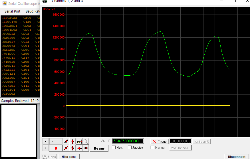
However, sometimes it shows me negative digitized value.

If this value is from the ratio (f_sensor/f_ref), it should not be negative, but it does.

Is this natural or am I misunderstood?

+Additional question)

I know that sensor frequency is represented as 1/2*pi*sqrt(L*C).

That means, if C is increased, then should sensor frequency decreased. Right?

I always have been observed that digitized value is increasing my stretchable sensor is extended.

However, this maybe contradiction that increasing of capacitance may cause decrease of sensor frequency.


Am I misunderstood? I would very thank you for answering my questions.

  • Hello DongWoo,

    Can you share some of the negative values you are reading back? The DATAx values are unsigned, so is it possible that some of the Arduino code is misinterpreting it as signed or two's complement data? You are correct that the DATAx values should never be negative.

    You are also correct that the sensor frequency should decrease when the capacitance increases. I suggest debugging the negative values first. The same error may be causing the output data to appear to be increasing, when the actual data is actually decreasing. If this behavior still occurs after you've debugged the other issue, then I suggest probing the INxA/INxB pins with an oscilloscope.

    Best Regards,

  • Here is Arduino open source code.


    #include <SPI.h>
    #include <Wire.h>
    #include <math.h>
    #include <stdio.h>

    #define DT 0.01 //Derivative threshold.
    #define IT 150 //Integration threshold.
    #define HAND 350 // Hand threshold.
    #define AVGN 10 //Degree of the IIR filter.
    #define L 1 //Leakege Factor.

    double p1 = 4.1269e-15;
    double p2 = -5.103e-10;
    double p3 = 8.869e-05;
    double p4 = 0.035609;

    long lasttime;
    byte FDC = 0x2B;// FDC address either 0x2A or 0x2B;
    byte MUX_CONFIG = 0x1B;

    byte CH0MSB = 0x00; //Most significant bits of the conversion result on channel 0. [11:0]-->>[27:16]
    byte CH0LSB = 0X01; //Less significant bits of the conversion result on channel 0. [15:0]-->>[15:0]
    byte CH1MSB = 0x02; //Most significant bits of the conversion result on channel 1. [11:0]-->>[27:16]
    byte CH1LSB = 0X03; //Less significant bits of the conversion result on channel 1. [15:0]-->>[15:0]
    byte CH2MSB = 0x04; //Most significant bits of the conversion result on channel 2. [11:0]-->>[27:16]
    byte CH2LSB = 0X05; //Less significant bits of the conversion result on channel 2. [15:0]-->>[15:0]
    byte CH3MSB = 0x06; //Most significant bits of the conversion result on channel 3. [11:0]-->>[27:16]
    byte CH3LSB = 0X07; //Less significant bits of the conversion result on channel 3. [15:0]-->>[15:0]

    void LedOn() {
    digitalWrite(2, HIGH);
    }

    void LedOff() {
    digitalWrite(2, LOW); //Target approaching!
    }

    //Build the complete conversion result from the specific channel

    unsigned long readChannel(int cnum) {
    unsigned long val = 0;
    word c = 0;
    word d = 0;

    if(cnum ==0){

    c = readValue(FDC, CH0MSB);
    d = readValue(FDC, CH0LSB);

    }else if(cnum==1){

    c = readValue(FDC, CH1MSB);
    d = readValue(FDC, CH1LSB);
    }else if(cnum==2){

    c = readValue(FDC, CH2MSB);
    d = readValue(FDC, CH2LSB);

    }else{

    c = readValue(FDC, CH3MSB);
    d = readValue(FDC, CH3LSB);

    }

    val = c;
    val <<= 16;
    val += d;

    return val;
    }

    //Read bytes from register channel specified

    word readValue (int FDC, int reg) {
    byte a = 0;
    byte b = 0;
    word value = 0;

    Wire.beginTransmission(FDC);
    Wire.write(reg);
    Wire.endTransmission();
    Wire.requestFrom(FDC, 2);
    while (Wire.available())

    {
    a = Wire.read();
    b = Wire.read();
    }

    value = a;
    value <<= 8;
    value += b;

    return value;
    }

    // IIR filter

    long average( unsigned long meassure, long avg_1, int n) {
    long avg = ((avg_1 * n) - avg_1 + meassure) / n;
    return avg;
    }

    void monitor() {

    double t = 0;
    double out = 0;

    long current[4] = {readChannel(0),readChannel(1),readChannel(2),readChannel(3)};
    long delta[4] = {0,0,0,0}, Integral[4] = {0,0,0,0}, Integral_1[4] = {0,0,0,0};
    long avg[4] = {0,0,0,0}, avg_1[4] = {0,0,0,0}, last[4] = {0,0,0,0};
    long last_val = {0};
    long current_val = {0};

    double result[4] = {0,0,0,0};

    for(;;){

    if(millis()-20 > lasttime){

    for(int i=0; i<3; i++){

    last[i] = current[i];// Shift register. The variable last will storage the current value for the next iteration.

    current[i] = average(readChannel(i), last[i], AVGN);//New value for current return from IIR filter --> function average(meassure, avg_1, n)

    //Derivative integration algorithm

    delta[i] = current[i] - last[i];

    if (abs(delta[i]) > DT) {
    Integral[i] = Integral_1[i] + delta[i];
    }

    else {
    Integral[i] = Integral_1[i];
    }

    if (abs(Integral[i]) >= IT && abs(Integral[i]) < HAND) {
    Integral_1[i] = Integral[i];
    }

    else {
    Integral_1[i] = Integral[i] * L;
    }

    //t = abs(Integral[i]);
    //result[i] = pow(t,3) * p1 + pow(t,2)*p2 + t*p3 + p4;

    if(i<2){
    Serial.print(-Integral[i]);
    Serial.print(" , ");
    }

    else{
    Serial.print(-Integral[i]);
    Serial.print(" , ");
    Serial.println(lasttime);
    }
    }

    lasttime = millis();

    }
    }
    }

    //Configuring the FDC2214

    void writeConfig(int FDC, byte reg, byte MSB, byte LSB) {
    Wire.beginTransmission(FDC);
    Wire.write(reg);
    Wire.write(MSB);
    Wire.write(LSB);
    Wire.endTransmission();
    }

    void Configuration() {

    writeConfig(FDC, 0x14, 0x20, 0x01);//CLOCK_DIVIDERS_CH0
    writeConfig(FDC, 0x15, 0x20, 0x01);//CLOCK_DIVIDERS_CH1
    writeConfig(FDC, 0x16, 0x20, 0x01);//CLOCK_DIVIDERS_CH2
    writeConfig(FDC, 0x17, 0x20, 0x01);//CLOCK_DIVIDERS_CH3

    writeConfig(FDC, 0x1E, 0xF8, 0x00);//DRIVE_CURRENT_CH0
    writeConfig(FDC, 0x1F, 0xF8, 0x00);//DRIVE_CURRENT_CH1
    writeConfig(FDC, 0x20, 0xF8, 0x00);//DRIVE_CURRENT_CH2
    writeConfig(FDC, 0x21, 0xF8, 0x00);//DRIVE_CURRENT_CH3

    writeConfig(FDC, 0x10, 0x00, 0x0A);//SETTLECOUNT_CH0
    writeConfig(FDC, 0x11, 0x00, 0x0A);//SETTLECOUNT_CH1
    writeConfig(FDC, 0x12, 0x00, 0x0A);//SETTLECOUNT_CH2
    writeConfig(FDC, 0x13, 0x00, 0x0A);//SETTLECOUNT_CH3

    writeConfig(FDC, 0x08, 0x69, 0xE8);//RCOUNT_CH0
    writeConfig(FDC, 0x09, 0x69, 0xE8);//RCOUNT_CH1
    writeConfig(FDC, 0x0A, 0x69, 0xE8);//RCOUNT_CH2
    writeConfig(FDC, 0x0B, 0x69, 0xE8);//RCOUNT_CH3

    writeConfig(FDC, 0x19, 0x00, 0x00);//ERROR_CONFIG
    writeConfig(FDC, 0x1B, 0xC2, 0x0D);//MUX_CONFIG
    writeConfig(FDC, 0x1A, 0x08, 0x01);//CONFIG
    //writeConfig(FDC, 0x1C, 0x80, 0x00);//RESET DEVICE
    }


    void setup() {
    Wire.begin();
    Serial.begin(115200);
    Serial.println("Starting");
    pinMode(2, OUTPUT);
    Configuration();
    lasttime=millis();
    }


    void loop() {

    Wire.beginTransmission(FDC);

    monitor();

    }

    With that code above, I confirmed that digitized value is increasing when the sensor is stretched (regardless of its sign). 

    I also confirmed that the capacitance value of my stretchable sensor is increasing when it is stretched (via LCR meter).

    Always thank you for kind answering.

    +Addition) Here is negative valued data.

    It appears randomly.

  • Hello DongWoo,

    Thank you for sharing the additional information. Can you clarify how you are getting the data above? Those numbers are very small and are not expected output values for the FDC2214. Are you calculating the sensor capacitance from the raw output data?

    Best Regards,

  • Oh, I forgot stretching sensor during observing. That was the value at the beginning of connection to the computer.

    Here is new information.

    Increase of curve means stretching is occurred and increase of capacitance.

    As your opinion, I want to try calculate the capacitance value from my sensor.

    But with this pattern, I`m not sure I can calculate original capacitance value from this data.

    (As my expectation and your opinion, it should be decreased when sensor is stretched.)

    Always thank you for your advice.

  • Hello DongWoo,

    Do you have an FDC2214EVM available? Can you try connecting your sensor to the EVM and monitoring the sensor frequency with the GUI? I'd like to see if the frequency increasing behavior still occurs with known hardware and software.

    Best Regards,

  • Thank you for your advice.

    I`ll let you know when same problem appears.

    Firstly, I need to buy EVM module, so it will take few days.

    Really thank you for supporting.