This thread has been locked.

If you have a related question, please click the "Ask a related question" button in the top right corner. The newly created question will be automatically linked to this question.

IWR1443: Adding CFAR to high accuracy lab

Part Number: IWR1443

I am trying to add the CFAR option to the high accuracy lab.  The intent is to place it after the first FFT to chose a particular peak, which may be different than the highest peak as found when using the MmwDemo_peakSearch() function.  Once a particular peak is chosen, that index would be copied to the maxIndex element of the rangeProcStats structure, and then the MmwDemo_processInterpolation() function woul dbe called to perform the zoom FFT.  Essentially, a version of the MmwDemo_processCfar() function from the lab0003-4k-fft project would be substituted for the MmwDemo_peakSearch() function in the high accuracy lab firmware.

To start, I added just the MmwDemo_CLICfarCfg() and MmwDemo_CLIPeakGroupingCfg() functions from the lab0003-4k-fft project.  I hard-coded values for the various parameters based on values that I found in various labs.  I find that if I set the peakGroupingCfg.inDopplerDirectionEn variable to either 0 or 1, the firmware runs but no chirps are performed.  Performing a search for inDopplerDirectionEn in both the SDK and the toolkit files does not result in finding a location where that variable is used that should affect the functioning of the firmware.  But obviously, there is some effect.

How can I find out why setting that enable variable to a valid value causes the firmware to not run correctly?

In the HWAutil_configCFAR() function of the 4k_fft lab, there is

    hwaParamCfg.source.srcRealComplex = HWA_SAMPLES_FORMAT_REAL;

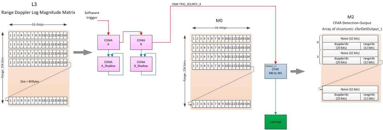
The source appears to come from the M0 buffer.  However, in the HWAutil_configRangeFFT() function used to configure the 1st FFT of that lab, there is

    hwaParamCfg[paramsetIdx].source.srcRealComplex = HWA_SAMPLES_FORMAT_COMPLEX; //complex data

That source also appears to be the M0 buffer.  It does not seem that there is anything that changes the M0 buffer between the call to the 1st FFT and the CFAR, so how is it that one function says M0 contains REAL data and the other says that is has COMPLEX data?

Matters are not helped that the high accuracy lab and the 4k_fft have different styles of coding.  That complicates trying to ensure that all of the necessary functions and statements needed for the CFAR have been copied from one lab to the other. 

I have asked in another post about documentation for the firmware.  I have the same question for this instance.  The Radar Hardware Accelerator User's Guide indicates details about the CFAR, but it does not give a clear description of how to link various paths through the HWA.  The 4k-fft lab uses a different set of settings for the first FFT than the high accuracy lab.  Therefore, the settings for the CFAR in the MmwDemo_configCFAR_HWA() function would need to be different than what is in the 4k-fft lab.  How to determine what those settings need to be?  What documentation describes that?

Best regards,

Alan


  • Hi Alan,

    I'm still looking into this, I'll be able to provide some guidance tomorrow.

    Cheers,

    Akash

  • Hi Alan,

    Would you be able to post a code snippet of how you are trying to implement this?

    As shown above the CFAR computation is performed in M0 and is output into M2 with a CFAR completion interrupt. This is described in the mmWave Doxygen, this specific page is at: C:/ti/mmwave_sdk_02_01_00_04/packages/ti/demo/xwr14xx/mmw/docs/doxygen/html/index.html#dataCFAR

    Cheers,

    Akash

  • Hello Akash,

    Essentially, what I would like to be able to do is to replace the peak search in the high accuracy lab with the CFAR.

            dataPathObj->firstPassHWADoneCnt++;//??

            if(dataPathObj->cliCfg->calibDcRangeSigCfg.enabled)
            {
                dataPathObj->dcRangeForcedDisableCntr++;
                MmwDemo_dcRangeSignatureCompensation(dataPathObj);
            }
            if(gHighAccuConfig.enableRangeLimit)
            {
                MmwDemo_rangeLimit(dataPathObj);
            }
            // amg
            // this can be used for First Echo
            {
    //            MmwDemo_processCfar(dataPathObj, &numDetectedObjects);
                // determine which peak index to use
                // copy peak index to 'MAX' statistics register
            }
            // amg
            // this can be used for Auto Largest threshold setting
            {
                MmwDemo_peakSearch(dataPathObj);
            }
            HWA_readStatsReg(dataPathObj->hwaHandle, &(dataPathObj->rangeProcStats), 1);
            MmwDemo_processInterpolation(dataPathObj);
    This is because our experience with through-air radar is that the largest peak does not necessarily correspond to the actual level location.  Sometimes, a multiple reflection of the level signal has a higher amplitude than the level signal.  Therefore is those circumstances, the first peak that is larger than a certain threshold is the actual level location rather than the largest peak.  So the CFAR would give us a list of candidate peaks, from which we would choose a peak to be used for the interpolation based on certain criteria.
    So, I added the two configuration functions from the 4k_fft lab:
    static int32_t MII_CFARCfg (void)
    {
        MmwDemo_CfarCfg   cfarCfg;
        /* Initialize the CFAR configuration: */
        memset ((void *)&cfarCfg, 0, sizeof(MmwDemo_CfarCfg));
        /* Populate configuration: */
        //procDirection           = (uint8_t) atoi (argv[1]);
        cfarCfg.averageMode     = MMW_HWA_NOISE_AVG_MODE;                   // HWA_NOISE_AVG_MODE_CFAR_CASO
        cfarCfg.winLen          = MMW_HWA_CFAR_WINDOW_LEN;                  // 8
        cfarCfg.guardLen        = MMW_HWA_CFAR_GUARD_LEN;                   // 4
        cfarCfg.noiseDivShift   = MMW_HWA_CFAR_NOISE_DIVISION_RIGHT_SHIFT;  // 3
        cfarCfg.cyclicMode      = 0;                                        // disabled
        cfarCfg.thresholdScale  = MMW_HWA_CFAR_THRESHOLD_SCALE;             // 0x4b0
        /* Save Configuration to use later */
        memcpy((void *)&gMmwMCB.dataPathObj.cliCfg->cfarCfg, (void *)&cfarCfg, sizeof(MmwDemo_CfarCfg));
        return 0;
    }
    int32_t MII_PeakGroupingCfg (void)
    {
        MmwDemo_PeakGroupingCfg peakGroupingCfg;
        int32_t numRangeBins;
        numRangeBins = gMmwMCB.dataPathObj.numRangeBins;
        memcpy((void *)&peakGroupingCfg, (void *)&gMmwMCB.dataPathObj.cliCfg->peakGroupingCfg,
            sizeof(MmwDemo_PeakGroupingCfg));
        /* Initialize the Peak Grouping configuration: */
    //    memset ((void *)&peakGroupingCfg, 0, sizeof(MmwDemo_PeakGroupingCfg));
        /* Populate configuration: */
        peakGroupingCfg.scheme               = 1;
        peakGroupingCfg.inRangeDirectionEn   = 0;
    //    peakGroupingCfg.inDopplerDirectionEn = 0;  // amg changing this to 0 causes chirps not to happen
    //    peakGroupingCfg.inDopplerDirectionEn = 1;  // amg changing this to 1 causes chirps not to happen
        peakGroupingCfg.minRangeIndex        = 0;
        peakGroupingCfg.maxRangeIndex        = numRangeBins - 1;
        if (peakGroupingCfg.scheme != 1 && peakGroupingCfg.scheme != 2)
        {
            System_printf ("Error: Invalid peak grouping scheme\n");
            return -1;
        }
        /* Save Configuration to use later */
        memcpy((void *)&gMmwMCB.dataPathObj.cliCfg->peakGroupingCfg, (void *)&peakGroupingCfg,
            sizeof(MmwDemo_PeakGroupingCfg));
        return 0;
    }
    I found that with just these two functions added, setting the peakGroupingCfg.inDopplerDirectionEn to either 0 or 1 resulted in no chirps being produced.  If I do not set that variable. as shown highlighted in red above, then the chirps happen and the system makes distance measurements.
     
    Once I can get past that issue, which was the original reason for this posting, I have a more fundamental issue.  The 4K_fft lab runs a 1D FFT, then a 2D FFT, then the CFAR.  We don’t need to run the 2D FFT as we will have only one Tx and Rx antenna.  Furthermore, we are likely to run and analyze one chirp at a time due to power constraints. rather than the multiple chirps of the 4k_fft lab.    So what is the L3 output of the 2D FFT as compared to the 1D FFT?  Are they the same, so that the CFAR can use either?  Or are they different and some translation or different setup of the CFAR is required depending on whether the 1D FFT or 2D FFT provides the input?  If different, can the 1D FFT be configured to provide data in the format for the CFAR without needing to run the 2D FFT?
     
    This kind of explanation is what I am having a hard time finding in the documentation.  Individual parameters and functions are described, but not how they need to be configured to interact with each other.  So while the labs are a big help in getting a system up and running, it's rather difficult to understand how to modify a lab to run with a different configuration.  I am reminded of the original DOS manual; great resource if you already know DOS, but not too helpful if you are new to DOS.
     
    Hopefully, this is a matter that such explanations exist, but I have not yet found them.
     
    Best regards,
     
    Alan
     
  • Hi Akash,

    In the HWAutil_configRangeFFT() function of the 4kfft lab, there is the following:

        /* enable the DMA hookup to this paramset so that data gets copied out */
        paramISRConfig.interruptTypeFlag = HWA_PARAMDONE_INTERRUPT_TYPE_DMA;
        paramISRConfig.dma.dstChannel = dmaDestChannelPing;  //TODO sync this define EDMA channel to trigger to copy the data out
        //paramISRConfig.cpu.callbackArg = paramSetSem;//TODO check if NULL is required
        errCode = HWA_enableParamSetInterrupt(handle,paramsetIdx,&paramISRConfig);
        if (errCode != 0)
        {
            //System_printf("Error: HWA_enableParamSetInterrupt(PING DMA) returned %d\n",errCode);
            MmwDemo_debugAssert (0);
            return;
        }
    

    I am assuming that the DMA is there to trigger the transfer from the MO memory to L3.  Is that correct?  Does the TODO comment in red mean that there something else that is needed to be done to the code besides what is in the existing firmware?

    Best regards,

    Alan

  • Hi Alan,

    Responses have been delayed due to holidays but we should have an answer for you sometime next week.

    Cheers,

    Akash

  • Hi Akash,

    Hope you had good holidays and BEST wishes for a happy new year!

    I was wondering if you had an idea when answers might be available for the several questions posed in this thread.  Having a timeline would help plan my activities for the next few weeks.

    Best regards,

    Alan

  • Hi Alan,

    An explanation for setting the peakGroupingCfg.inDopplerDirectionEn variable might be that the High Accuracy Lab does no Doppler processing, only Range Processing. Is there an implication to not setting this variable? You had mentioned that the sensor chirps and reports distances. This variable is only set in the Out Of Box (mmw_cli.c, 223) and Vital Signs Lab (cli.c, 336)  for the IWR1443 demos.

    To the second question, the CFAR will need to be reconfigured since Range and Doppler are stored in the L3 together (see my diagram above). If you'd like to discuss this further then I would like to get another expert involved. Would you be able to open up a new thread with part number IWR1443 with context around the Out-Of-Box demo, not 4K or High Accuracy Labs.

    Also it appears the TODO comments were left in the code unintentionally, thank you for pointing this out.

    Cheers,

    Akash

  • Hi Akash,

    Thanks for your response.  I will be on travel for the next two weeks, so will not be able to attend to this until the first week in February.  When I return, I will set up a new thread as you suggest and add a diagram of what I am trying to do.

    Best regards,

    Alan

  • This sounds good, thank you Alan!

    Cheers,

    Akash