This thread has been locked.

If you have a related question, please click the "Ask a related question" button in the top right corner. The newly created question will be automatically linked to this question.

IWR1443: About Interference Detection Capability with IWR1443 or IWR1642

Part Number: IWR1443
Other Parts Discussed in Thread: IWR1642, AWR1243,

Hello

I am thinking about using the interference detection function of IWR1443 or IWR1642.
Please tell me the following questions.

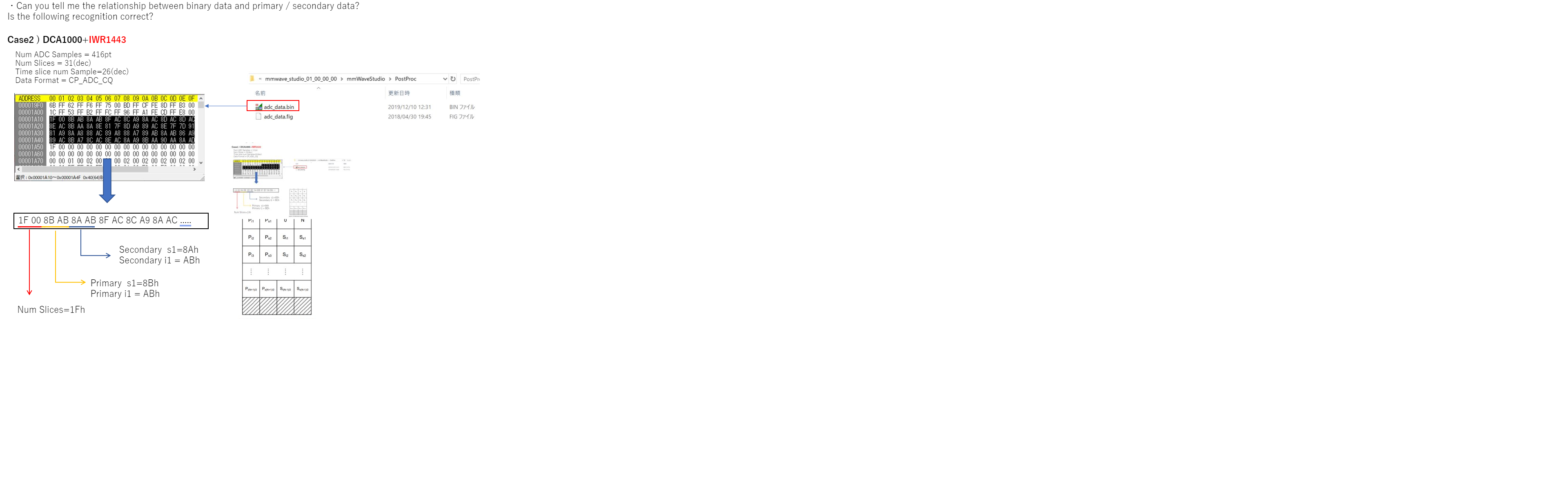
・Can you tell me the relationship between binary data and primary / secondary data?
Is the following recognition correct?
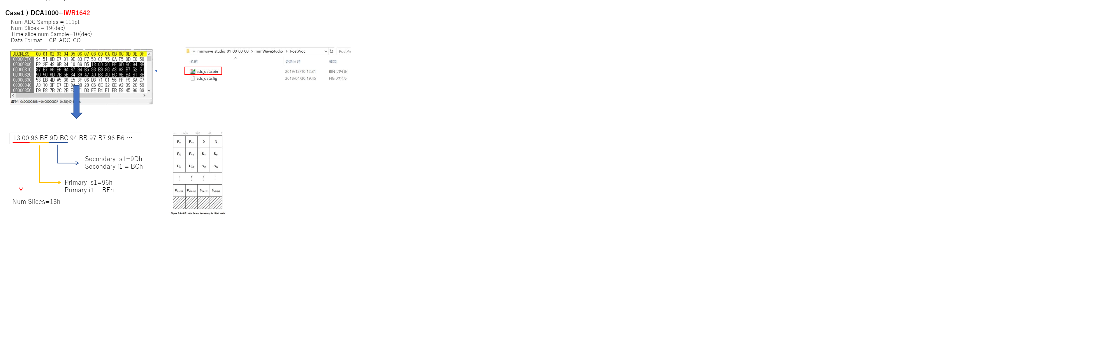
(case1)
The conditions are described below.

DCA1000+IWR1642
Num ADC Samples = 111pt
Num Slices = 19(dec)
Time slice num Sample=10(dec)
Data Format = CP_ADC_CQ


(case2)
The conditions are described below.

DCA1000+IWR1443
Num ADC Samples = 416pt
Num Slices = 31(dec)
Time slice num Sample=26(dec)
Data Format = CP_ADC_CQ


・the time slices consist of “Primary” and “Secondary”.
Would you tell me purpose of “Secondary” time slice.


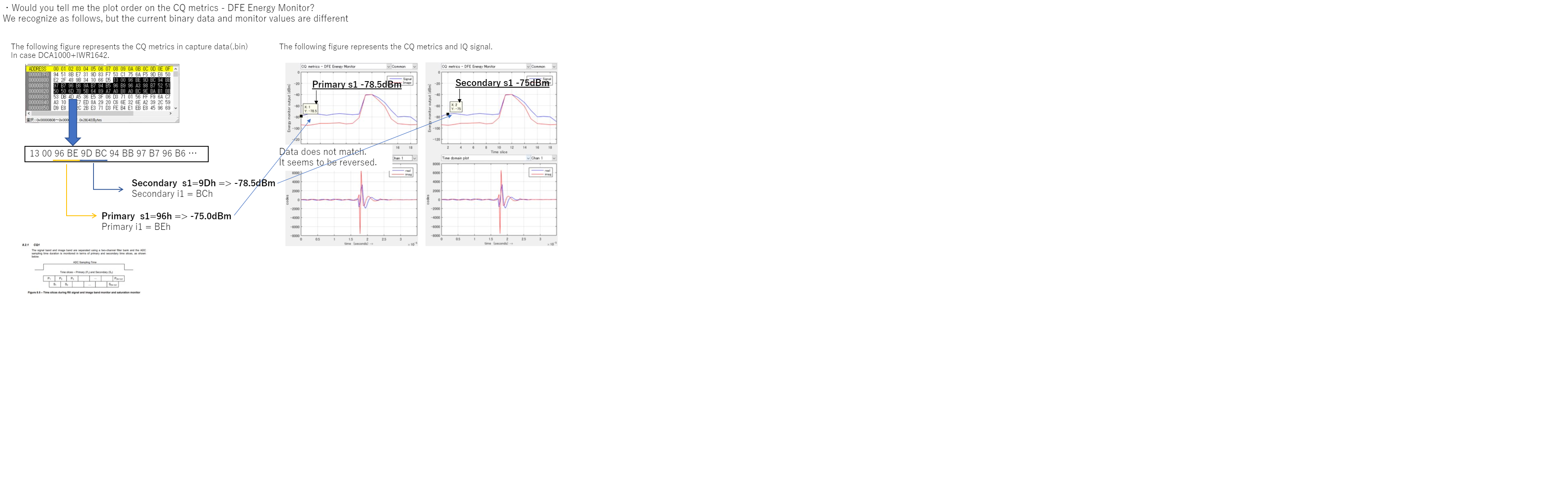
・Would you tell me the plot order on the CQ metrics - DFE Energy Monitor?
We recognize as follows, but the current binary data and monitor values are different

Regards

  • Attach the drawing because it could not be attached.

  • Hi User,

    I've asked an expert to look into this and we should have an answer for you in the next few days.


    Cheers,

    Akash

  • HI, there:

    You are quite a pioneer in using this feature.  Can you let me know which document have you found the useful information about CQ?  

    Best,

    Zigang

  • Dear Akash
    Thank you for your reply....
    Please tell me when the answer comes.
    keisuke tanaka.
  • Hi Zigang

    The URL of the material I investigated is attached below.

    https://training.ti.com/jp/mmwave-awr1x-interference-detection-crucial-step-effective-mitigation

    https://e2e.ti.com/cfs-file/__key/communityserver-discussions-components-

    files/1023/1205.AWR1xx_5F00_Radar_5F00_Interface_5F00_Control.pdf
     
    AWR1243: Question about Image Rejection and image band interference monitor

    keisuke tanaka.

  • HI, Keisuke:

    The primary and secondary covers slightly different ADC samples.  For example, when you have 416 samples, and one slide is 26 sample,

    Then you have primary covers 

    P1: sample 1 ~ 26

    P2: sample 27~52

    The secondary covers:

    S1: samples 14~39

    S2: samples 39~63

    and etc.  

    So, it gives you a little bit more information.   Let me know whether you data makes more sense now.

    Best,

    Zigang

  • Hi Zigang
    Sorry for the late reply.
    And thank you for your comment.
    but I do not understand well the relationship with the question that I am asking this time.
    I'm sorry, Could you be a bit more specific with what you're telling ?
    keisuke tanaka.
  • HI, 

    My previous response was just trying to explain why we need both primary slice and secondary slice. 

    Your interpolation looks right to me based on the document.  I will have to repeat the capture myself to see whether I see the same mismatch.  Will get back to you later.

    Best,

    Zigang 

  • HI, 

    Sorry for the delay.   I was not able to duplicate your measurement.  On radar studio,  the CQ config is fixed and I can not change.   And I can not match the CQ data from adc_data.bin with CQ metrics curve at all.   Do you use radar studio to do data capture?   

    At the same time, I will forward your ticket to the design team to get some feedback. 

    Best,

    Zigang 

  • hi,ZIgang
    Thank you for your reply.
    I'm sorry to be late.
    I will respond to your questions.
    Q:Do you use radar studio to do data capture?
    A:Because there are no evaluation components, we currently use mmwave(DCA1000), but finally we are considering access from DSP.
    I know that the data format changes depending on whether you use mmwavestdio or DSP.
    I want to know the data format when using mmwavestdio and DSP.
    keisuke tanaka
  • Is my following understanding right?

    You have found the document about the CQ data format in DSP, and it matches well with the memory content.   But when you look at mmwave radar Studio output (the post processing curve), it does not match well, right?   You want to understand why they are not matching, right?

    I am confused, how can you look at the memory in DSP and looked at the results in radar studio at the same time?

    Best,

    Zigang

  • hi,ZIgang
    thank you for your reply.
    Sorry at the lack of explanation.
    The content I want to hear is exactly what is said.
    I thought that the reason why the CQ data and the CQ metric curve did not match was because I did not understand the data format correctly. I was asking for the data format for that.
    Also, although I could not answer in the previous question, I am currently acquiring the CQ data of adc_data.bin with the configuration of IWR1443 + DCA1000. However, for the CQ metric curve, I use a tool that I created based on the data obtained.
    Regarding DSP, my view is that the data format differs between the IWR1443 + DCA1000 configuration and the IWR1443 + DSP configuration. Therefore, I would like to tell you if the data format configuration differs between the above two configurations, and asked a question.
    keisuke tanaka
  • Hi, Tanaka:

    Sorry for the delay. The CQ plots in radar studio is not formally tested and supported.   And I can not get my side of setup working even as good as yours.  I was using DCA1000 + EVM + radar studio.

    Best,

    Zigang

  • Hi,Zigang

    Thank you for your reply.

    We output ADC_CP_DATA using IWR1443Boost + DCA1000, and verified using our own CQ display tool using the data.

    Does the fact that the mmwaveStdio CQ plots are not officially tested and supported mean that the ADC_CP_DATA output from the DCA1000 is also unreliable data?
      Or is ADC_CP_DATA reliable but mmwaveStdio's CQ plot display unreliable?
    If ADC_CP_DATA is reliable, please tell me the data format.

    keisuke tanaka

  • Hi, 

    The CQ plots are not officially tested and supported.  If you are using radar studio to do data capture, the data format is listed in the document below: http://www.ti.com/lit/an/swra555/swra555.pdf.  But every section regarding CQ monitoring is marked with TBD.  So, I will check with the design team and let you know.

    Are you using radar studio?

    Best,

    Zigang

  • HI,Zigang
    Thank you for your reply.
    We are using the DCA1000 and mmwavestdio to get ADC_CQ_DATA.
    It is the URL that you told me, but I think this is the format when you get ADC_CQ_DATA without using DCA1000. Is it OK to think of the same format both via DCA1000 and directly to IWR1xxx?
    (DCA1000 data format(
    At least the format of ADC_DATA is different between via DCA1000 and directly accessing IWR1xxx.
    Keisuke tanaka
  • HI, 

    You are right.  The data format in the linked document is only valid for the data access through CCS.  

    For the radar studio, the data will format in the following way:


    CP_data

    -          4 bytes (ADC_CP or CP_ADC or CP_ADC_CQ mode).

    -          0 bytes (ADC mode)

    CQ_data

    -          0 bytes (ADC, ADC_CP or CP_ADC).

    -          Ceil((cq_val * 16 / numAdcBits)) bytes (CP_ADC_CQ mode)

    Where cq_val = CQ0TransSize + CQ1TransSize + CQ2TransSize (given in Data path configuration), numAdcBits = 12/14/16

    One chirp data should be with following order: 

    1)      Two 16-bit CP for RX0

    2)      Then a chirp of ADC sample of IQ data for RX0

    3)      Then two 16-bit CP for RX1

    4)      Then a chirp of ADC sample of IQ data for RX1

    5)      Then two 16-bits CP for RX2

    6)      Then a chirp of ADC sample of IQ data for RX2

    7)      Then two 16-bit CP for RX3

    8)      Then a chirp of ADC sample of IQ data for RX3

    9)      Then followed with CQ data.

    Let me know whether it makes sense

    Best,

    Zigang

  • HI,Zigang

    Thank you for your response. It was helpful.

    But,I want to know the details of (9.Then followed with CQ data).
    I recognize the following flow, is that OK?
    1) Num Slices: 1byte
    2) 0: 1 byte
    3) Ps1: 1 byte
    4) Pi1: 1 byte
    5) Ss1: 1 byte
    6) Si1: 1byte
    7) Ps2: 1byte
    8) Pi2: 1byte
    5) Ss2: 1byte
    6) Si2: 1byte
    ...
    Keisuke Tanaka
  • HI,

    It is little bit tricky.  I believe when the data saved in DSP, it is in the format.   But when it read back through LVDS, it can be tricky.  For example, the complex ADC data for IWR1642 in DSP is saved in the order of

    I0, Q0, I1, Q1, I2, Q2, I3, Q3, and etc

    However, when writing to LVDS, 

    LVDS lane 1 takes: I0, I1, I2, I3

    LVDS lane 2: takes Q0, Q1, Q2, Q3

    At the output of radar studio, the binary data format is:

    I0, I1, Q0, Q1, I2, I3, Q2, Q3.

    So it is different between these two order.   I am not sure for CP_ADC_CQ data, is it following the same order change.   I notice that CP and ADC is following the same change. But I am not sure about CQ yet.

    Best,

    Zigang

  • Can you check if you reorder the CQ data the same way, whether it explains the CQ plot you have seen before.

    Best,

    Zigang