This thread has been locked.

If you have a related question, please click the "Ask a related question" button in the top right corner. The newly created question will be automatically linked to this question.

Compiler/LMP91000: LMP91000:

Part Number: LMP91000

Tool/software: TI C/C++ Compiler

Dears,


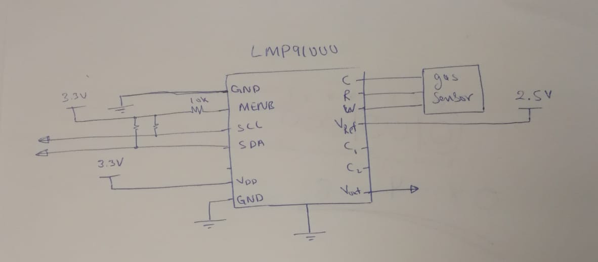
We are working in our project where we are trying to use you chip (LMP91000) to read the Oxygen concentration using Euro-Gas micro O2 sensor.


In fact, we changed the parameters to be compatible with the gas sensor but there is not change in Vout pin.


Could you please help us to understand what is wrong with setting that we did and what are the setting that are going to work with our sensor.


Please, find data sheet of the oxygen sensor that we are using.


We are looking forward to your kind help and support...


Regards,O2_SS_Micro (0-25%).pdf

  • user6246305,

      Can you send me a schematic and an outline of the setting you made, so I can review your setup to see what might be the problem?


  • Mode Control Register (Address 0x12) : ( 00000011 ) : ( 0x03)

    Status Register (Address 0x00)

    Protection Register (Address 0x01)

    TIA Control Register (Address 0x10) : ( 00010111 ) : ( 0x17 )

    Reference Control Register (Address 0x11) : ( 01001010 ) : ( 0x4A )


    #include <LMP91000.h>


    #include <LMP91000.h>

    #include <Wire.h>


    LMP91000 pstat = LMP91000();


    void setup()

    {

    Wire.begin();

    Wire.setClock(100000);


    Serial.begin(9600);


    Serial.println("Start >>>");


    Wire.beginTransmission(0x48); // transmit to device #8

    Wire.write(0x01);             // sends one byte

    Wire.write(0x00);             // sends one byte

    Wire.endTransmission();   // stop transmitting

    delay(500);

    Serial.println("Enable Writing is Done");


    Control(0x12, 0x03, "Mode Control is Done");

    Control(0x10, 0x17, "Enable TIA Control is Done");

    Control(0x11, 0x4A, "Enablereferance Control is Done");  

    }


    void loop()

    {


    }


    void Control(byte Register, byte Value, String Message)

    {

    Wire.beginTransmission(0x48); // transmit to device #8

    Wire.write(Register);             // sends one byte

    Wire.write(Value);             // sends one byte

    Wire.endTransmission();   // stop transmitting

    delay(500);


    Serial.println(Message);

    delay(200);

    String str1 = String(Register, HEX);

    Serial.print("Stored data in ( 0x");

    Serial.print(str1);

    Serial.print(" ) is equal to : 0x");

    int Data = pstat.read(Register);

    String str2 = String(Data, HEX);

    Serial.println(str2);

    delay(200);

    }

  • Dear, Gordon Varney

    We are still watting to your kind help and support.

  • user6246305,

        the MENB pin is pulled high and left high. (MENB  Module Enable, Active-Low) Look at the timing chart below. You have to pull this pin low or it will not respond to I2C.

  • We pulled MENB low, still not change in Vout pin (no response)

  • user6246305,

      What are the pull up resistor values you are using for the I2C pins?

    Have you looked at the I2C pins to verify that the data waveforms looks good?

    Have you hooked up a protocol analyzer (or I2C shark) to verify that the data is good going into the LMP91000?

    Please send scope shots of the communications if possible.

  • What are the pull up resistor values you are using for the I2C pins?

    First we use 6.8k then we use 100k .

    Have you looked at the I2C pins to verify that the data waveforms looks good?

    No ,

    Have you hooked up a protocol analyzer (or I2C shark) to verify that the data is good going into the LMP91000?

    We have to contact where we read the main address and read all values in the registers. But there is not change and no reading from gas sensor.

  • My first thought is 10k pull ups is probably your best choice for pull-up resistors.

    It would be good to look at the data waveforms to verify that the edges and levels are good. If you can send a scope shot of the data that would help.

  • What is the VOUT voltage that you are measuring?

    Also try Mode Control Register (Address 0x12) : ( 00000111 ) : ( 0x07)

    What is the VOUT measuring in this mode? 

  • Read back the Status register. What value are you getting? If you are not getting a 0x01 then the LMP91000 is not ready to accept I2C writes. You should be reading this register before trying to write the others.

    Also make sure the Lock register is set to 0x00 to write the other registers. A 0x01 will put it in read only mode.

  • What is the VOUT voltage that you are measuring?

    2.21 V

    Also try Mode Control Register (Address 0x12) : ( 00000111 ) : ( 0x07)

    What is the VOUT measuring in this mode? 

    1.38 V

  • What is the VOUT voltage that you are measuring?

    2.21 V

    Also try Mode Control Register (Address 0x12) : ( 00000111 ) : ( 0x07)

    What is the VOUT measuring in this mode? 

    1.38 V


  • Dear user6246305 - 

    You may want to consider changing the setting for 0x10 through 0x12 registers.

    I examined the settings using the 02-A2 sensor from Alphasense, mounted on the LMP91000 EVM, using 0x03 for 0x12, 0xC0 or 0xC1 for 0x11 and 0x0E for 0x10, this allowed a correct current level from the sensor and corresponding O2 and voltage levels from the GUI. 

  • finally , its working fine , 

    Wire.beginTransmission(0x48); // transmit to device #8
    Wire.write(0x01); // sends one byte
    Wire.write(0x00); // sends one byte
    Wire.endTransmission(); // stop transmitting
    delay(500);
    Serial.println("Enable Writing is Done");

    Control(0x12, 0x03, "Mode Control is Done");

    Control(0x10, 0xF, "Enable TIA Control is Done");

    Control(0x11, 0x4D, "Enablereferance Control is Done")

    best regards ,,

    Hassan AL-Nasser