This thread has been locked.

If you have a related question, please click the "Ask a related question" button in the top right corner. The newly created question will be automatically linked to this question.

IWR1443: Custom IWR1443PCB board UniFlash serial debugging download

Part Number: IWR1443
Other Parts Discussed in Thread: UNIFLASH,

Hello aozer,

We have customized a PCB for IWR1443. We have removed the XDS110 chip on the board, and we want to load the PCB out of the box with an external emulator (such as XDS100V2). Option 1: 1. We saw you reply that you can use XDS110 emulator, but I don't know if XDS100V2 can replace XDS110? Are they programming PCB custom versions through UniFlash?
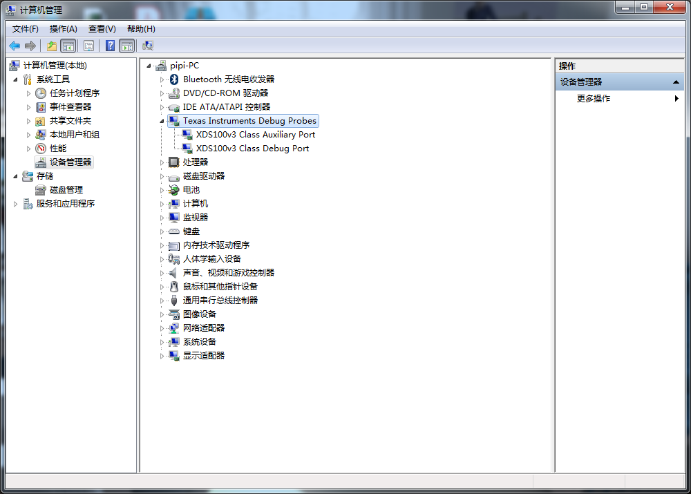
2. If I use UniFlash for programming, but when we connect the XDS100V2 emulator, the computer cannot recognize the COM port? What should we do?
Option 2: 1. We use a USB to TTL RS232 interface, but the computer can only recognize one COM port. Do you know that there will be two COM ports when using the IWR1443BOOST module, what should we do?
2. When using UniFlash, what chip model and address should we choose?

Regards,

Javid

  • Hi,

    1. Is there a reason you need to use the  XDS100V2  instead of the  XDS110?
    2. For the computer to recognize the COM port you need to install the drivers for the emulators, was that done?
    3. You need to choose the IWR1443 and the COM port for the user UART

    BR,

    Charles O

  • Hi,Charles O

    I am glad to hear from you!

    1.The reason is that we don't currently have an XDS110 emulator, but we have XDS100V2, XDS100V3 and XDS510. If these emulators cannot replace the XDS110, please let me know.

    2.We have installed the driver for the emulator, but the computer does not recognize the COM port (as shown below). You know, When I connect TI's IWR1334 BOOST, there will be two COM ports. What should I do to make the computer recognize the COM port?

    3.In other words, I lead 3 wires (AR_RS232TX, AR_RS232RX, GND) from the interface of the IWR1443 development board. Can I use them to download out-of-the-box demo configuration files to the development board?

    Regards,

    Javid

  • The TX, RX and GND pins are what you need for flashing. You also need to ensure that the SOP pin is set to flashing mode to successfully flash the board.