This thread has been locked.

If you have a related question, please click the "Ask a related question" button in the top right corner. The newly created question will be automatically linked to this question.

IWR6843: ES2.0 ADC phase problem

Part Number: IWR6843

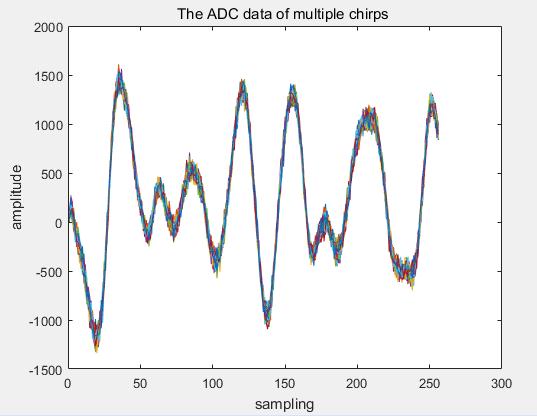
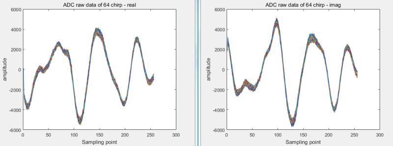
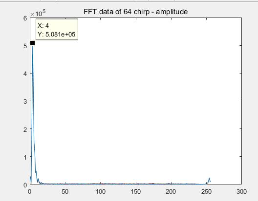
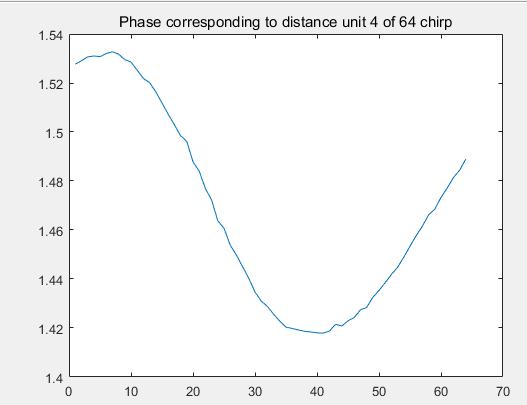
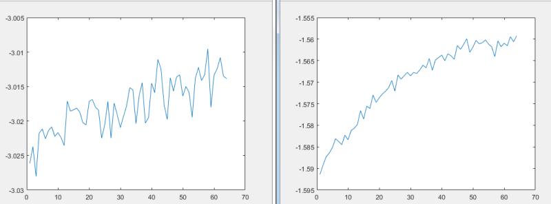
We use iwr6843 to do target detection and collect ADC raw data. For a fixed target, the radar is in a completely static state, and the target is in a completely static state. For multiple chirp data of the same antenna channel of a frame (such as the number of chirps is 64). After doing FFT of distance dimension, the phase of the target's signal will suddenly change in a chirp. Theoretically, the radar is still, the target is still, and the phase of the target echo should be relatively stable between different chirps in the same frame, and the time of phase jump is random. ES1.0 Without this problem.Why is this happening now in ES 2.0?

  • HI, 

    Yes, it does not make sense that the static data is jumping between the chirps.   Here is my suggestions:

    Can you plot the ADC data on top of each other for different chirp and see whether you observe the similar jumping? 

    Can you also explain how did you get the phase of a target over chirps?    

    Can you also send out the chirp parameter for review? 

    Is your target a strong target, and is there any other interference near by?

    Best,

    Zigang

  • Hi ,

    1、The ADC data of multiple chirps can not see the jump, but the phase noise is not very ideal

    2、FFT the ADC data of each chirp, find the distance unit of the target and find the phase of the signal

    3、parameter:
    sampling rate:12MHz
    chirp rate   :9MHz/us
    Single chirp sampling points :256
    Chirp number :64
     
    4、The target signal is very strong, and there is no other interference signal

  • HI, 

    Can you plot the real and imaginary ADC data separately to double check?

    Can you plot the range FFT output to see how big is the peak associate with the target?

    Can you plot the real and imaginary of the range FFT output separately to check?

    best,

    Zigang

  • Hi ,

       ADC raw data  ,FFT data of 64 chirp -amplitude

      The fundamental reason lies in the poor phase determination of the radar received signal. But the ES1.0 didn't have that problem.

  • HI, 

    Your recent phase figure shows the variation from 1.42 ~ 1.53 rad.  It is not the same as the original one that have a big jump from 1.369 to 2.627 rad.   

    Are we talking about the same setup and same target?  

    Best,

    Zigang

  • Hi,

    It's not the same target, but it's all static. It means a stationary target, which may have a jump or other unstable phase change

  • HI, 

    The big phase jump looks shock to me, I feel it should be something wrong with the setup.  The smaller phase jump is something worth to compare with ES1.  Can you repeat the same process with ES1 and send me the phase variation of the same target?

    By the way, please send me the complete chirp/frame configuration, including center frequency and etc.

    Best,

    Zigang

  • Hi,

    Es1.0 on the left and es2.0 on the right. Phase of the same target

    ES1.0 and ES2.0 waveform configurations are the same

    sampling rate:12MHz
    chirp rate   :9MHz/us
    Single chirp sampling points :256
    Chirp number :64

    f0=61GHz 

    idle time=9,adcstarttime=30,endtime=60,txstarttime=1,FRAME_PERIODICITY_VAL=100

    2T4R

  • HI, 

    Thank you for your confirmation.   We do found that at 61.2G, ES2 board has a small clock spur.   ES1 board has a bigger clock spur at 62.1G.   So ES1 and ES2 are different.  Is it possbile to move away from the 61.2G, say move start frequency to 61.21G?  This problem will also goes away if you have a wider RF bandwidth, say 1GHz bandwidth. 

    Best,

    Zigang