Other Parts Discussed in Thread: , LDC1312, LDC1614EVM
Hello there,
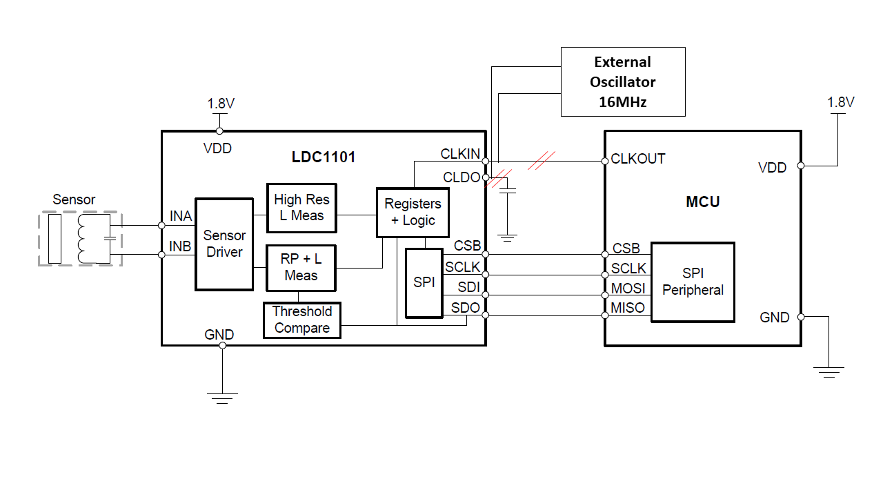
I have few questions about LDC1101 using as main component for future eddy current sensor in closed loop system. So far I performed basic tests with LDC1101EVM through TI GUI.
I am seeking to use one of LDC for sensor which must have following parameters:
Sampling rate: 20kHz, fixed conversion time
Repeatability: <+-5um
Sensing Range: 0.2-2 mm
Operating temperature: 0-60C
Target: Aluminium block which has more than 3 times bigger diameter than sensor. Thickness 4+ mm.
Resolution: >= 12bits
Following assumption I made, please commend if I approached correctly:
Based on sampling rate LDC1101 is only LDC device capable of high enough sampling rate. Next fastest option is LDC1312 but the maximum sample rate is limited up to: 13.3 kSPS.
Fixed conversion time works only for LHR measurement mode. Rp or Rp+L measurements change based on sensor frequency which is unfortunately useless for real time controller. There has to be fixed conversion time. Also LHR measurement is not that significantly influenced by temperature change as Rp measurement which has to have some temperature compensation.
Sensor diameter should be at least twice the size of maximum range. I need only 2 mm which would be 4 mm diameter of sensor coil. But in manuals is written, use as big diameter as fits the design. I use default coil which has 14 mm diameter, 15 turns, 0.15 mm spacing and trace width. It has 4 layers 2x2 parallel. 390pF capacitor.
What is optimum sensor diameter and other parameters? Should I used wire wound coil, should be there ferrite core? I can fit even diameter of 20mm if needed.
Q should be as high as possible.
Filling ratio at least 0.3, bigger is better.
Inductance should be high or it does not really matter? I understand it that higher the change in frequency higher resolution I get. Also it is better to have lower LC sensor frequency because I can fit more cycles of reference clock in it and it makes measurement more precise.
Does parallel sensor coil configuration have any positive effect on LHR measurement? (manual snoa930a.pdf recommends it for Rp measurement).
I performed repeatability test in static mode (10 times reached 4 position 0.3-1.2 mm with default sensor). Register 0x30 - 2E and 0x31 - 0. Reference clock 12 MHz, LHR measurement only. Target was aluminium 70x70 mm. Default coil diameter 14 mm.
I understand that crucial is equation for conversion time of LHR mode. (snosd01d.pdf eq. 14)
t_conv = (55 + RCOUNT*16)/f_CLKIN
One of the limitation is f_CLKIN which is now 12MHz. It can be changed up to 16MHz which should decrease conversion time by 1/4 with keeping same performance. Is default reference clock precise enough or is it only for evaluation purposes? Precision of reference clock is also one of the main component which can influence overall performance.
I read manual snoa941a, 3 heading: In addition, the LDC1101’s LHR (High-resolution inductance mode) measurements have an effective reference frequency of 32 MHz (when the external reference frequency is set to the maximum supported 16MHz). Does the LDC1101 support even higher reference frequency then 16MHz?
RCOUNT is set: 46, Register hex code: 2E. in order to have sample rate >20kHz (20.22756kHz). I assumed that there would be 16MHz ref clock. Now the sample rate is smaller but it should have still same performance.
I got these results:
300um +- 4.06868um (3_SIGMA)
600um +- 10.71658um (3_SIGMA)
900um +- 12.20337um (3_SIGMA)
1200um +- 22.97813um (3_SIGMA)
Unfortunately at this configuration I did not get performance I need. Repeatablity rapidly decreases with increase of distance and sample rate which I understand but is there still some way how it could be improved? Or am I on the edge of performance possibilities? Would custom made sensor coil improve overall performance?
Thank you very much for your response and any suggestions.
Best Regards,
Michael