This thread has been locked.

If you have a related question, please click the "Ask a related question" button in the top right corner. The newly created question will be automatically linked to this question.

AWR1642: Reference Design Footprints

Part Number: AWR1642

Hi All,

I am working with AWR1642BOOST evaluation board, and i have just noticed that in the reference design they not used the recommended land-pattern for some components.

part number(GCM21BR71A106KE22L) with case code "21" must have this dimensions for land pattern,

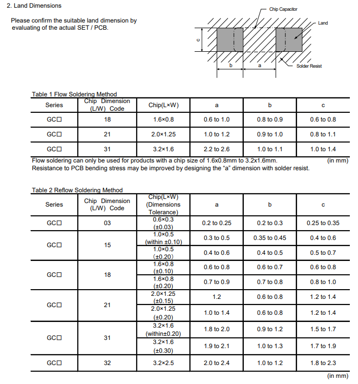
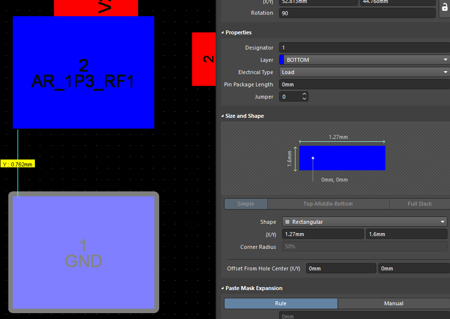
And here is the foot print used in the reference design,

So is this variation between the used one and the recommended is normal?

And I am also wondering if TI send to manufacturer the same reference design they provided to customers, or they send another one with some changes on footprints dimensions for example?

Thanks

Basel

  • HI,

    We have to check with the PCB design team and get back to you

    Thank you

    cesar

  • Hello Basel,

    We have an Altium librarian team who handles all footprint requests for our Atlium components libraries so I think for the GCM21BR71A106KE22L they just used a standard 0805 footprint rather than following the specified land pattern in the datasheet. 

    The design files we provide online are the exact same files that we provide to our PCB manufacturer, so there is no difference between the files you have and the files that our vendor has. We have not seen any issues with reflow of any components on our PCB, but I would recommend to always follow the recommended land pattern in the datasheet if you do happen to see any discrepancies. 

    Regards,

    Adrian

  • Thanks a lot :)