This thread has been locked.

If you have a related question, please click the "Ask a related question" button in the top right corner. The newly created question will be automatically linked to this question.

CCS/AWR1243: AWR1243: Antenna array element layout and spacing

Part Number: AWR1243

Tool/software: Code Composer Studio

Dear TI expert,

we have several problems about the AWR1243 cascade board’s antenna array element layout,

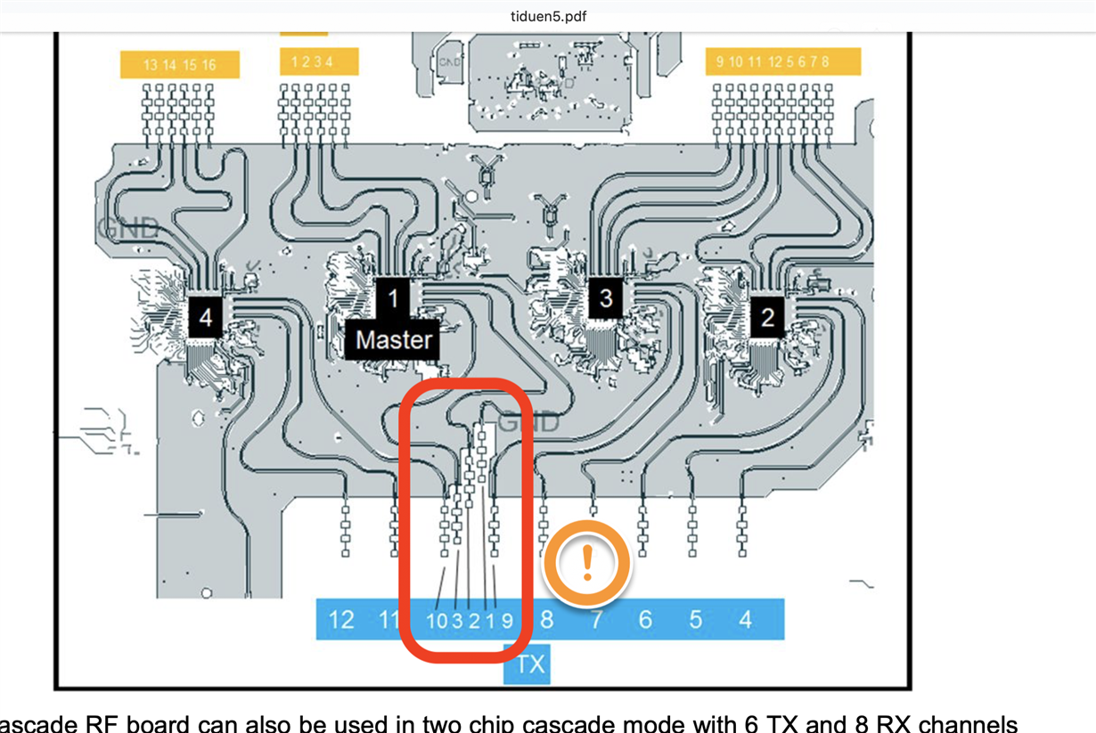
1. AWR1243P‘s elevation antenna must be placed in the middle of the antenna plate ?

figure 1

2. why the distance  among the AWR1243P‘s elevation antenna elements is B2=0.5*wavelength, B3 = 1.5*wavelength,B4 = 1.0*wavelength ?

figure 2

3.  in the figure 1, why the chip layout is chip4,chip1(master),chip2,chip3 ?

not chip1,chip2,chip3,chip4 or other layout order ?

is there have to use the master chip’s antenna to estimate elevation angle ?


many thanks 

  • Hello ,

    The antenna array placement is something you can choose and decide based on your system requirements and implementation. What we have on our EVM just one example and its not mandatory to follow the same. Depending on your system requirements and algorithms you can change it. 

    You can refer to the following app note to understand the basics of angle estimations and angular resolution (same basic apply to azimuth and elevation angle estimation) : http://www.ti.com/lit/an/swra553/swra553.pdf

    Having a non uniform antenna spacing allows for a better angular resolution. That is why for elevation we have used non uniform antenna spacing.

    Regards,

    Vivek 

  • Hi Vivek,

    When we use AWR1243 into our own application,To modify the layout of the array,

    Can we use one of the slaves chip's three transmitter antennas are  placed at elevation direction and use them to estimate elevation angle? 


    many thanks


  • Hello,

    Yes, you can change the antenna pattern to use the slave device Tx for elevation.

    Regards,

    vivek