This thread has been locked.

If you have a related question, please click the "Ask a related question" button in the top right corner. The newly created question will be automatically linked to this question.

IWR6843: Fractions of DCA1000 data

Part Number: IWR6843

Hi

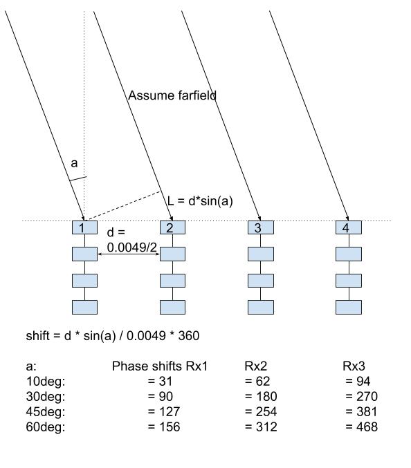
I am still trying to extract the phases of the individual Rx antennas.

To do so, I have two antennas, running CW:s at a certain offset facing each other.

I have a dca1000 connected to one IWR6843 reading out the ADC raw data from it while in CW mode (we have this working)

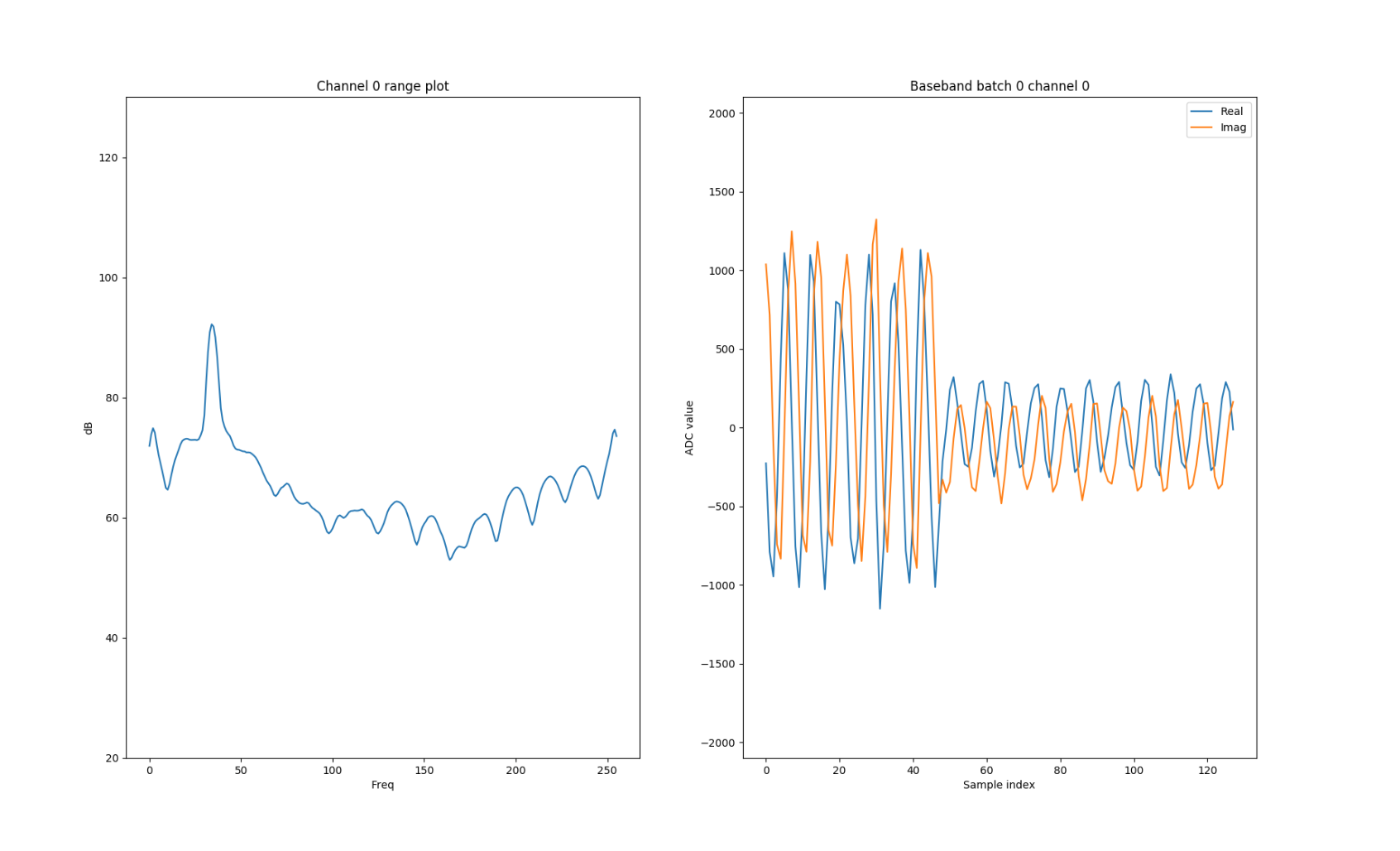
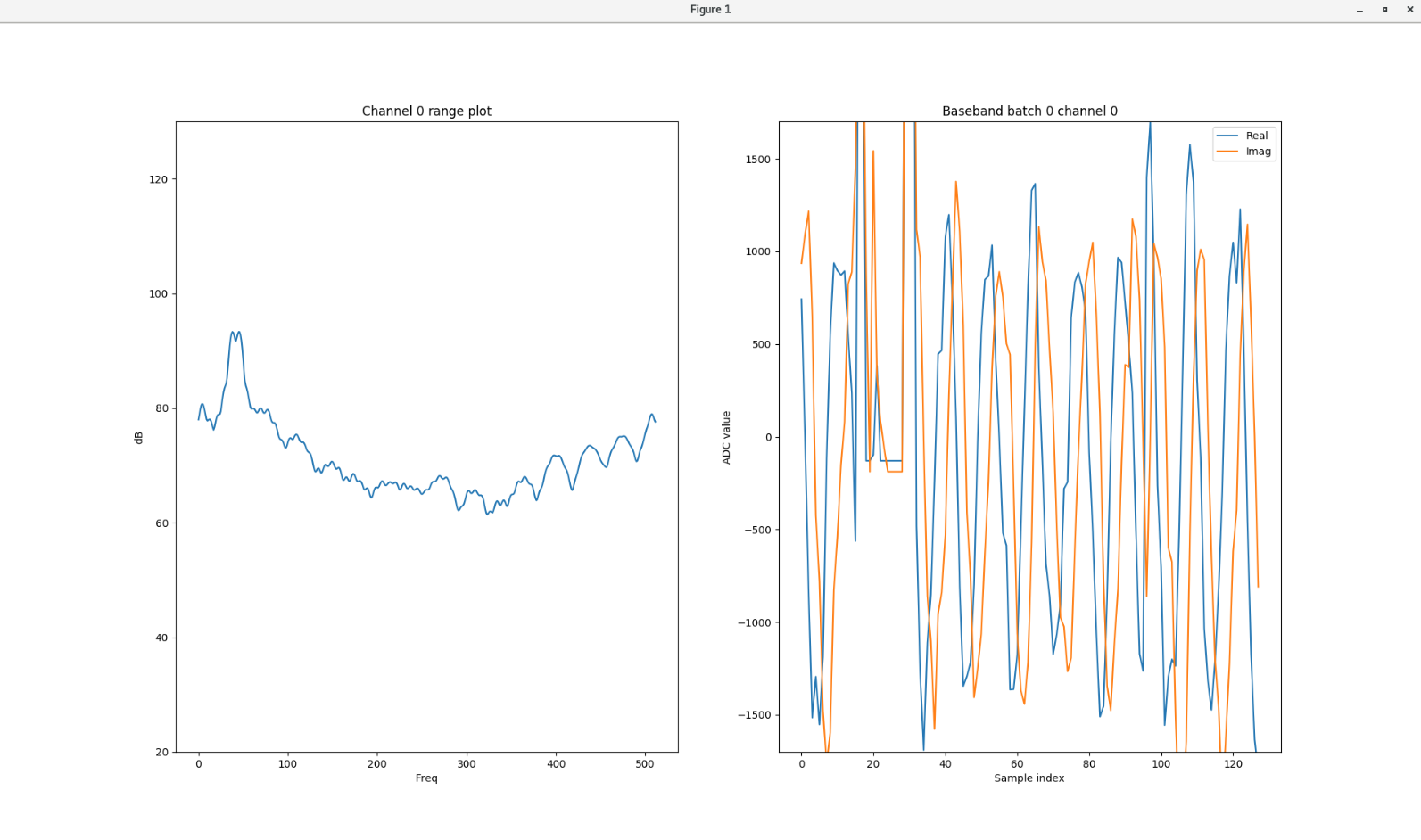
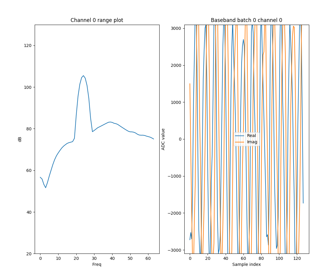
but when looking at the baseband the data looks to odd.

It look like sometimes the data is a mix of two different chirp data, see image. I am expecting one good looking sinus wave.

I have tried enabling the HSI header to mark the beginning of every frame but this does not seem to help.

Can you point me in any direction of how to find out why the data looks broken?

Here is some code creating the plots (Python)

    r_win = np.blackman(conf['n_samp'])

    for frame_index, data in data_loader.read_frames():

        cube = data['cube']
        cube -= np.mean(cube, axis=0, keepdims=True)  # remove DC

        r_cube = np.fft.fft(cube * r_win.reshape(-1, 1, 1), axis=0, n=conf['ran_n_fft'])

        # incoherent integration in doppler to improve SNR
        dop_result = np.mean(np.abs(r_cube), axis=1)

        plt.clf()

        plt.subplot(121)
        plt.plot(20 * np.log10(np.abs(dop_result[:, 0])))
        plt.title('Channel 0 range plot')
        plt.ylabel('dB')
        plt.xlabel('Freq')
        plt.ylim(20, 130)

        plt.subplot(122)
        plt.plot(np.real(cube[:, 0, 0]), label='Real')
        plt.plot(np.imag(cube[:, 0, 0]), label='Imag')
        plt.title('Baseband batch 0 channel 0')
        plt.ylabel('ADC value')
        plt.xlabel('Sample index')
        plt.legend()
        plt.ylim(-2100, 2100)

        plt.pause(0.01)

------------------------------------------------------------------------------------

This is my current configuration for the IWR6843 with the DCA1000 board.

sensorStop
flushCfg
dfeDataOutputMode 2
channelCfg 15 2 0
adcCfg 2 1
adcbufCfg -1 0 1 1 1
lowPower 0 0
contModeCfg 61.245350 0 0 2000 0 0 30 1 128
% contModeCfg 61.246 0 0 3125 0 0 30 1 128
% contModeCfg 61.25040625 0 0 3125 0 0 30 1 128
guiMonitor -1 1 1 1 0 0 1
cfarCfg -1 0 2 8 4 3 0 100 0
cfarCfg -1 1 0 4 2 3 1 100 0
multiObjBeamForming -1 1 0.5
calibDcRangeSig -1 0 -5 8 256
clutterRemoval -1 0
compRangeBiasAndRxChanPhase 0.0 1 0 1 0 1 0 1 0 1 0 1 0 1 0 1 0 1 0 1 0 1 0 1 0
measureRangeBiasAndRxChanPhase 0 1. 0.2
aoaFovCfg -1 -90 90 -90 90
cfarFovCfg -1 0 0 45
cfarFovCfg -1 1 -10 10
extendedMaxVelocity -1 0
CQRxSatMonitor 0 3 4 63 0
CQSigImgMonitor 0 127 4
analogMonitor 0 0
lvdsStreamCfg -1 1 1 0
bpmCfg -1 0 0 0
sensorStart

  • HI, 

    As I mentioned the two sensors have independent clock.  And the clock frequency can be move from time to time.  You will have different frequency offset between the two sensors at any given time.   I am not sure what to expect.   Maybe you can try to use the same external clock to serve both sensors.   The crystal on the EVM board has large variation up to 100ppm. So RF frequency difference between the two sensors can be as large as 60G*200e-6 = 12MHz. 

    What is these two figures?  Are they captures over two different time?

    By the way, what are you trying to achieve here?  

    Best,

    Zigang

  • The two different IWR6843 might drift but that does not matter in my setup.

    All that matters is the raw adc data output from the DCA1000 from one of the boards. It should be one single sinus wave if I understand it correctly, but it looks to me that the data I see is either scrambled or data from two different chirps and the broken part of the wave in the plots (right subplots) is where one chirp begins and the other ends.

    The two plots are of the same setup at two different points in time.

    The left plot is the result of the FFT and the right one the real and imaginary part of the raw data for the first chirp from Rx0.

    I am trying to extract data to be used to see the phase difference for the 4 Rx:s. After processing the data, I expect something like the image (using Rx0 as reference with a phase shift of 0 degrees).

  • HI, 

    For RX channel characterization, our characterization team uses a signal generator and up-converter and horn antenna to transmit continuous wave.   And at the receive side, we use external clock to sync with the signal generator clock.  

    Sorry, we can not support you with your method. 

    Best,

    Zigang

  • Thanks for your input.

    We figured out that the data was broken by the DCA1000. Too much data in to little time it seemed.

    We solved it by resetting the DCA1000 connection for every measurement and reading and discarding 5 frames before taking the measurement data from the DCA1000.

    This resulted in good looking baseband plots.

    We will continue on to use this data to calculate the phase differences of the different Rx antennas now.