This thread has been locked.

If you have a related question, please click the "Ask a related question" button in the top right corner. The newly created question will be automatically linked to this question.

AWR1243: AWR1243 Cascade start anomaly

Part Number: AWR1243
Other Parts Discussed in Thread: TDA2

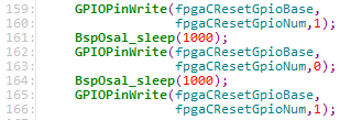
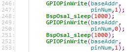
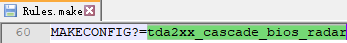
The SDK I used is PROCESSOR_SDK_RADAR_03_07_00_00, I didn't change the code inside, the only modification is:

After compiling, I put the MLO (C:PROCESSOR_SDK_RADAR_03_07_00_00\vision_sdk\binaries\apps\tda2xxx-cascade-radar)
and the AppImage (C:\PROCESSOR_SDK_RADAR_03_07_00_00\vision_sdk\binaries\apps\tda2xx_Cascade_bios_radar\vision_sdk\bin\tda2xx-evm\sbl_boot)
into the SD card and boot.The mode I chose are as follows:

Vision SDK Usecases: 1: RADAR Usecases
RADAR Usecases: a: Cascade RADAR (4 AWR1243) Capture + RADAR Object Detect (DSP) + NetworkTx (TDA2xx Only)
2D FFT Core Selection: 2: EVE
Select Network Mode: 1: TFDTP

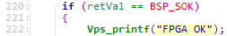
After that, there is a high probability that the last line shown below will not be printed:

At this point, part of the radar code can work normally, but the AlgorithmLink_radarProcessProcess() function in
C: PROCESSOR_SDK_RADAR_03_07_00_00\vision_sdk\apps\SRC\rtos\radar\SRC\alg_plugins\radarprocesslink_algplugin.c
will not be executed, so the radar does not work normally.

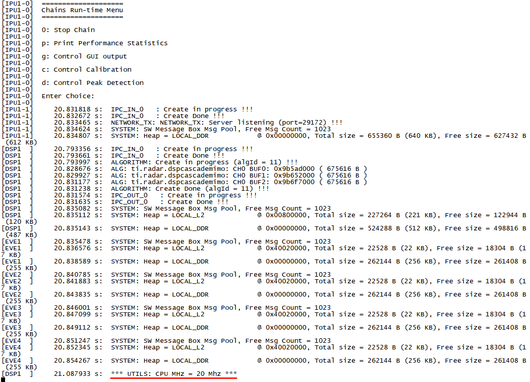
If I keep rebooting the radar, eventually
*** UTILS: CPU MHz = 20 MHz ***
will be printed and the radar will working normally.

What should I do to avoid this?

thank you very much

best regards

  • The path of MLO is C:\PROCESSOR_SDK_RADAR_03_07_00_00\vision_sdk\binaries\apps\tda2xx_cascade_bios_radar\sbl\sd\opp_high\tda2xx-cascade-radar

  • This sounds like HW issue.

    If you reboot a few time, everything is working fine, correct?

  • Yes, and  I debugged the code, feeling that the reason might be that the DSP was not working properly.

  • On the back of the cascade processor board, there are 4 LED lights with labels such as "FPGA1 CDONE", "FPGA2 CDONE", "FGPA3 CDONE", and "FPGA4 CDONE".

    When the board is not working, could you check if those LED lights are ON?

  • The "FPGA2 CDONE" light did not on when the radar is not working:

    And if this light is on,  the radar will be working everytime:

    So that's probably why. What should I do to solve this problem?

    thank you very much.

  • I replaced another cascade processor board, but I still have the same problem. It is difficult to know the specific reason...

  • Hi,

    I replaced another cascade processor board, but I still have the same problem. It is difficult to know the specific reason..

    Regards.

  • Thanks for confirming the issue.

    When the LED is not on, it means that particular FPGA failed to come out of reset.

    FPGA is the bridge to transfer Radar data coming from AWR CSI2 output to TDA2 VIP parallel input port.

    So if FPGA didn't come out the reset properly, no radar data will be received by TDA2.

    There is one FPGA for one radar so 4 total. All need to be working for the use case to run on TDA2.

    The source code which handles the FPGA reset sequence is under ~/vision_sdk/apps/src/rtos/radar/src/common/chains_common_cascade_fpga.c.

    If you want to experiment any way to avoid this issue, you can simply try changing all "BspOsal_sleep(100)" to "BspOsal_sleep(1000)" in the above file so the delay increases from 100ms to 1s.

    Regards,
    Stanley

  • I changed all of the BspOsal_sleep(100) to BspOsal_sleep(1000),  there are four places:

    and I wrote this:

    So I can confirm that the code was successfully modified.

    But the problem remains...Is there any other way to avoid this problem?

    I really need to solve this problem as soon as possible. Thank you very much.

    Regards,
     J G1

  • Unfortunately, I don't have a board which can exhibit this issue consistently so I have to experiment on your board.

    I think the problem may just be ChainsCommon_fpgaPowerUp() function. Try commenting out 159-161 lines as the followings.

    Under line 150...

        gpio_pad_config[0].pin_num = fpgaCResetPad;
        configure_pad(gpio_pad_config, sizeof (gpio_pad_config) /
                  sizeof (gpio_pad_config[0]));
        GPIOModuleEnable(fpgaCResetGpioBase);
        GPIODirModeSet(
                fpgaCResetGpioBase,
                fpgaCResetGpioNum,
                GPIO_DIR_OUTPUT);
    
    #if 0
        GPIOPinWrite(fpgaCResetGpioBase,
                     fpgaCResetGpioNum,1);
        BspOsal_sleep(100);
    #endif
        GPIOPinWrite(fpgaCResetGpioBase,
                     fpgaCResetGpioNum,0);
        BspOsal_sleep(100);
        GPIOPinWrite(fpgaCResetGpioBase,
                     fpgaCResetGpioNum,1);


    The idea is the FPGA was under reset due to pull-down and we set the reset line high -> low -> high.

    This triggers 2 resets to FPGA back-to-back. By removing the first one, there will only be one reset left.

    We can see if this makes the initialization more stable.

    Regards,
    Stanley

  • Thanks for your reply!

    I tried that, and also made the delay increases from 100ms to 1s. The chances of this happening have decreased, but it's still possible.

    From my observations, it seems to be more likely to occur when the radar is first activated after it has been out of power for some time.

    The temperature here is about 10 degrees celsius. I turned off the radar for about 30 minutes and then turned it back on. I tried four times and failed to activate the radar each time.

    But after every boot failure, if I keep rebooting the radar, after one to three times, it will be succeed. After that, seems like every boot will be successful (not 100% sure).

    Is there anything else I can try?

    Regards,
     J G1

  • The reset sequence doesn't seem to be the problem.

    I don't think we can determine the issue without the FPGA vendor.

    At the moment, I would suggest you to implement a check for FPGA CDONE signal which indicates if FPGA is functional after reset. If not, simply stop the use case and reboot the board.

    From the schematics, you can see GPIO2_23/GPIO2_26/GPIO2_27/GPIO2_24 are connected to 4 FPGA CDONE signals repectively.

    You can read the status after the FGPA reset is released.

    If CDONE doesn't go high ('1'), the FGPA will not be functional.

    At this point, you can stop the use case and reboot the board.

  • In the past few days, I found a phenomenon that if I power off the radar and then power on again when the FPGA was not started normally for the first time, it would take many, many times for the FPGA to start successfully.

    But if I restart the radar by pressing the reset button, it only takes 1 or 2 times for the FPGA to start successfully.

    Does that help you analyze the cause of the problem?

    I have 2 TDA2xx boards, they all have this problem, it doesn't seem normal.

    Regards,
     JG

  • Could you try to toggle FPGA Flash Reset line to see if it helps?

  • Hi, 

    I am experiencing the same problem, but in my case  both FPGA2  and FPGA3 do not start properly (LEDS do not switch on)

    Sara Salvador

  • Hi,

    when you say "reboot the board", do you mean HW reboot ? Or is there a way to SW-reboot ? I tried to simply power up again the FPGA but still it doesn't start....

    Sara

  • I meant Power cycle the board.

  • Isn't there any software trick to power cycle the board ? A watchdog or something like that ?

    Sara

  • The issue is with FPGA, not TDA2 SoC, and it has to be power cycle.