This thread has been locked.

If you have a related question, please click the "Ask a related question" button in the top right corner. The newly created question will be automatically linked to this question.

IWR6843ISK: Unable to connect to Demo Visualizer using IWR6843ISK

Part Number: IWR6843ISK
Other Parts Discussed in Thread: UNIFLASH, , TIDA-010022, MMWAVEICBOOST, TIDA-01022

Hi there,

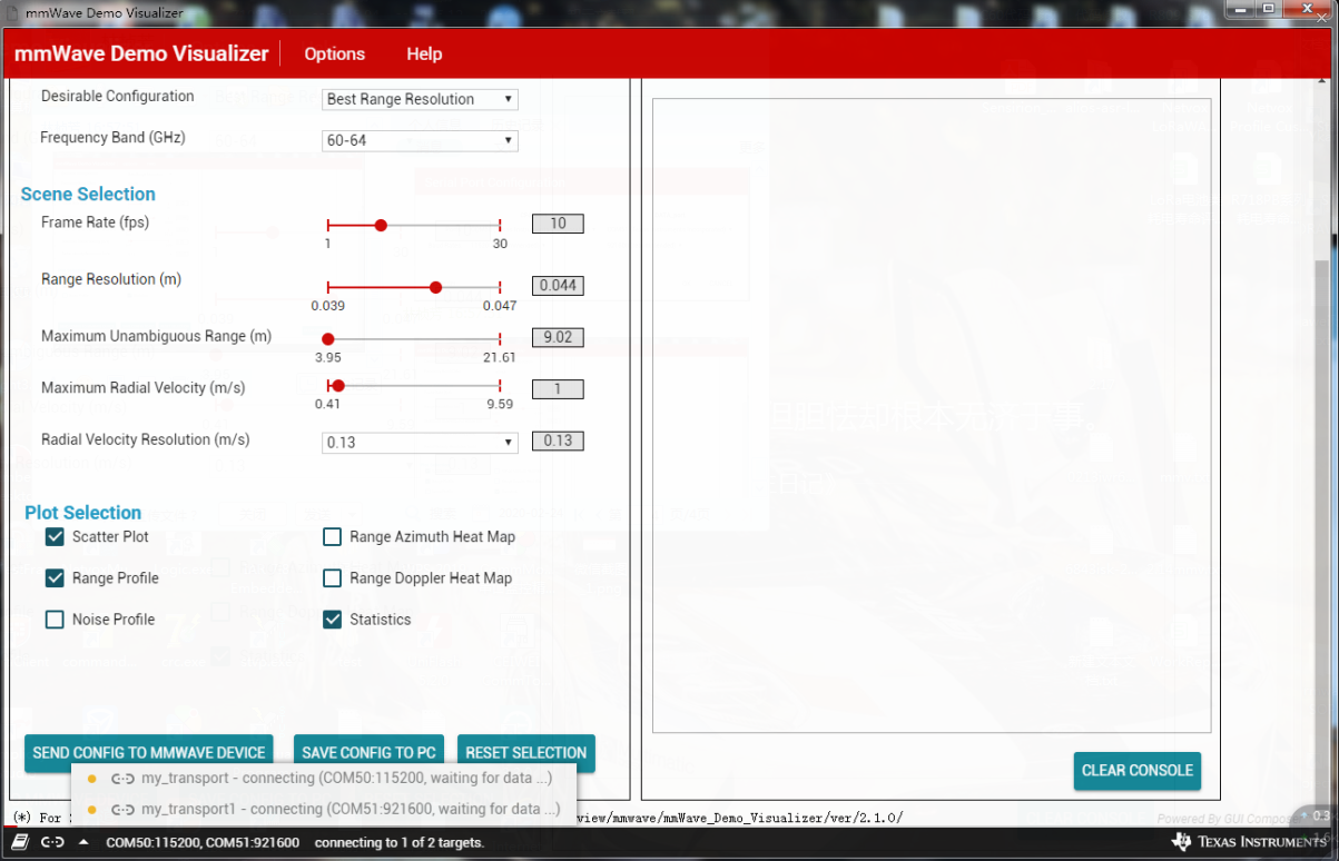
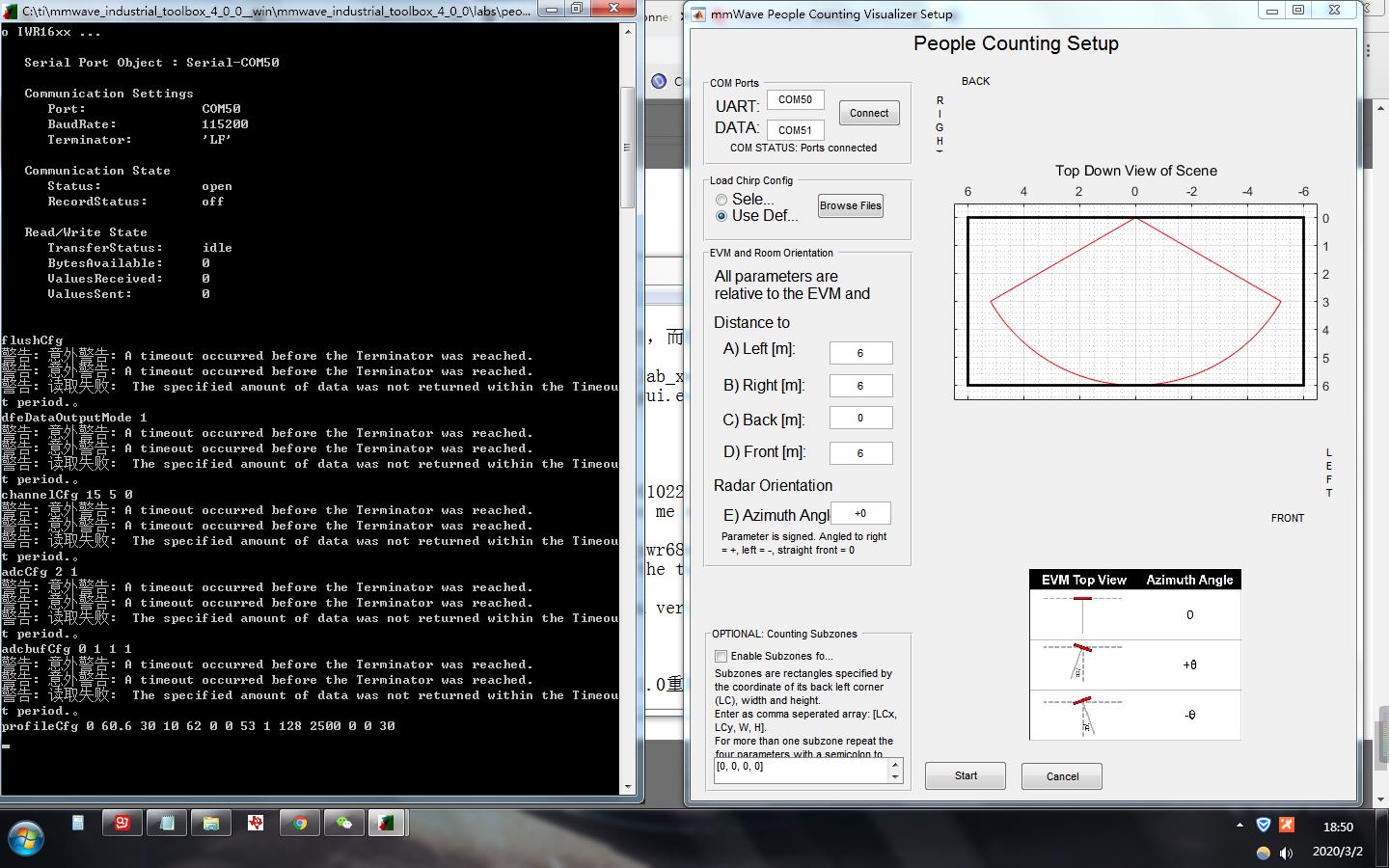
I am unable to connect my IWR6843ISK to the demo visualizer.I am able to use uniflash to flash the pplcount lab xwr68x.bin file of iwr6843isk in the lab, and then use the pplcount gui.exe program to get the point cloud map.During the setup of the IWR6843ISK i have correctly using the correct serial port. But whenever i press "send config to the mmwave device" it will show that com port 50 and com port 51 is "waiting for data". I hope I can get help, thank you very much, looking forward to your reply.

Thanks.

  • Hi,

    You are using the wrong visualizer. Please read the manual.

    Regards,

    Justin

  • Hi,Justin .
    I am able to use uniflash to flash the 3D_people_count_68xx_demo.bin file of iwr6843isk in the lab, and then run the mmWave_People_Counting_GUISetup.exe program.But when I successfully connected to the serial port and pressed "send configuration", nothing happened to 3d plot.Even as I walked around the sensor's detection area, he still had no data changes.I sincerely hope to get your advice and reply. Thank you very much.

  • Hi,Justin .
    I am able to use uniflash to flash the 3D_people_count_68xx_demo.bin file of iwr6843isk in the lab, and then run the mmWave_People_Counting_GUISetup.exe program.But when I successfully connected to the serial port and pressed "send configuration", nothing happened to 3d plot.Even as I walked around the sensor's detection area, he still had no data changes.I sincerely hope to get your advice and reply. Thank you very much.

    thanks !

  • Hi,

    Your device is probably not responding to the configuration file. First, lets confirm that is true without the gui:

    1. Connect you device to an application like Tera Term (tera term works well on windows for this)
    2. Connect to the UART Com port, set baud rate to 115200
    3. If you reset the device, you should see output similar to this:
    4. If you do get output, you can try sending the config to the device using tera term. Set the newline delay to be 100 msec
    5. Open another tera term terminal on the DATA Com port - if you see random data coming across, then the device is sending data
    6. LED on the device should blink if it is tracking someone.

    If you get to step 3 and do not see any message in tera term the device is not booting properly. It is usually one of these issues:

    1. Power Supply is not compatible (need 5V 3A) - values too high or too low can cause the board to function improperly
    2. Device is not set to functional mode (make sure to remove SOP2 and hit the reset button)
    3. Device is ES1 - see the user's guide to determine revision

    Let me know if you need more help.

    Regards,

    Justin

  • Hi,Justin .
    First, I determined that my power supply was 5V 3A and my device was ES2.
    1. I used uniflash to put 3d_people_count_68xx_demo.bin file flash into iwr6843isk evm, and removed the sop2 jumper and clicked reset button to enter function mode.Start the Tera Term program to connect to the UART COM port, set the baud rate to 115200, press the reset button of the device, and there is no response in the display window of Tera Term.


    2. In order to eliminate the problem of the device itself, I burned down the previous pplcount_lab_xwr68xx.bin file and did the same operation as above, and found that the Tera Term display window responded.

    thanks!

  • Hi, Justin.
    I really need your help.
    How do you configure a device to use tera or other serial port tool terms?Are there any relevant documents and codes for reference?
    I sincerely hope to get your advice and reply. Thank you very much.

    thanks.

  • Hi,

    Tera term is really just a serial port utility - you can use it to send or receive data - its useful for debugging. You can configure the device with it if you want to, just paste the configuration file into it.

    Back to your problem - the prebuilt binary should work since the device is ES2 and has the correct power supply. I would recommend using Code Composer Studio to rebuild the binary incase there was some corruption during the install process of the toolbox.

    Regards,

    Justin

  • Hi,Justin .

    I really need your help.
    I tried to rebuild the.bin file using Code Composer Studio 8.1.0 or reinstall the toolkit, but still could not get the image data correctly.
    This time I chose the configuration document, but every time I pressed the "send configuration" button, the visualizer failed to respond.


    thanks!

  • Hi,Justin .

    I really need your help.
    I want to use IWR6843ISK EVM flash tida-010022 pc_lab_xwr68xx.bin file and run it successfully on the device, hoping to solve the following two problems.
    1. Which visualizer should I use to observe the trajectory and point cloud map of the human body?
    When I used mmwave_people_counting_guisetu.exe, the result was the same as before, even without the GUI.
    2. Can use serial port tool to send commands, configure relevant parameters, start sensors and read data.
    Is there any relevant document for reference?

    I am currently using:

    IWR6843ISK (ES2.0) + MMWAVEICBOOST
    Code Composer Studio 8.1.0
    mmwave_industrial_toolbox_4_1_0
    mmwave_industrial_toolbox_4_2_0
    mmwave_sdk_03_03_00_03
    uniflash_5.2.0
    mmWave_Demo_Visualizer 3.3.0
    MATLAB Runtime 2017a(9.2)


    I sincerely hope to get your advice and reply. Thank you very much.
    thanks!

  • Hi,

    I can think of a few potential issues:

    1. The com ports you have entered may be flipped.
    2. The computer is blocking access to the com ports, so that the gui application cannot use them. This is common with unregistered software, and can usually be fixed by running as admin.
    3. The wrong configuration is being sent (I think you already confirmed you were using the correct configuration and setup)

    To use the TIDA-01022, please download an older version of the toolbox. Version 4.0.0 is best. You can select different version of the toolbox from the TI Resource Explorer page. Once you have this, run lab "68xx_people_counting" - this is the same software used in TIDA-01022. This comes with a Matlab gui - see if this one works for you.

    Regards,

    Justin

  • Hi, Justin.
    First of all, you mentioned tida-01022 in your description, and I mentioned tida-010022, which makes me not sure if we are talking about the same thing.


    Second, I first flash the pc_lab_xwr68xx.bin file of tida-010022((http://www.ti.com.cn/tool/cn/TIDA-010022?keyMatch=%E4%BA%BA%E5%91%98%E8%AE%A1%E6%95%B0&tisearch=Search-CN-everything)), and test it with pplcount_gui.exe of the toolbox. Version 4.0.0, and still find the error.

    Finally, I want to send the corresponding command through the serial assistant to start the detection mode of iwr6843isk evm and get the detection data such as the speed of the human body.Is there any documentation about the command for reference? Where can I see it?The question is urgent,I hope to get your help. Thank you very much.

    Thanks!

  • Hi,

    As mentioned, the binary included in TIDA-010022 is only confirmed to work with the CC1352 device that transmits data back to the host. Please download Industrial Toolbox version 3.6.2 or 4.0.0 and use the 68xx_People_Counting lab. This is the same software, but the output works with the Matlab visualizer.

    Regards,

    Justin

  • Hi, Justin.
    According to your description, I flash the.bin file of 68xx_People_Counting in 4.0.0 of the Industrial Toolbox version, and use.exe to get the cloud map.But there are still the following two questions, I hope to get your help.
    1. As you said, is the pc_lab_xwr68xx.bin file in the tida-010022 Firmware file I downloaded through tida-010022 the same as the pplcount_lab_xwr68xx.bin file in the 68xx_People_Counting experiment in the Industrial Toolbox version 4.0.0?

    2. I want to send the corresponding command through the serial assistant to start the detection mode of iwr6843isk evm and get the detection data such as the speed passed by the human body.
    Is there any documentation about the command for reference? Where can I see it?


    I hope to get your help. Thank you very much.
    Thanks!

  • Hi,

    1. The core functionality of the software is the same, but the software included with TIDA-010022 has been modified to interface with the CC1352 EVM. So performance will be the same (although the software on Industrial Toolbox has received more updates, so it may perform better).
    2. The commands are described in the mmWave SDK User's guide. If you can't find a command there, it is described in the pplcount_customization_guide.pdf document included with the lab.

    Regards,

    Justin

  • Hi, Justin.


    I still need your help.
    Now I want to communicate the MCU with IWR6843ISK EVM to configure and retrieve the data.Which pin should I connect to the IWR6843ISK?
    I hope to get your help. Thank you very much.


    Thanks!

  • Hi, Justin.


    I still need your help.
    Now I want to communicate the MCU with IWR6843ISK EVM to configure and retrieve the data.Which pin should I connect to the IWR6843ISK EVM?


    I hope to get your help. Thank you very much.


    Thanks!

  • Hi,

    Please see the EVM user's guide for instructions on setting the Switches to BP/LP mode and which pin to connect to. Look for the RS232 lines and MSS Logger.

    Regards,

    Justin

  • Hi, Justin.
    I still need your help.
    First of all, I have read EVM user's guide. I have the following questions to ask you.
    1.MMWAVEICBOOST has two serial ports, one is FTDI_USB serial port and the other is XDS110USB serial port. Which serial port should I use?

    2. I used the XDS110USB serial port before, and realized the operation of flash memory and pplcount_gui.exe to view the point cloud map, now I want to achieve my goal of communication between the MCU and IWR6843ISK EVM.
    Which pin should I connect my module to the IWR6843ISK EVM?
    Which is the configuration pin?
    Which is the data output pin?
    What is the communication protocol between them?

    3. I tried to connect the logic analyzer to 5 pin and 7 pin of J5, and observed the data output of serial port data com51, but there was no corresponding waveform and data on the pin.
    I tried 17 and 19 pins in J5 and found the same results.
    Did I pick the wrong pin?

    I hope to get your help. Thank you very much.
    Thanks!

  • Hi,

    You should be using pins 5 and 7 for the UART Com Port (used to configure the device) and pin 9 on J6 (MSS LOGGER) to get the DATA COM Port out. Make sure Tx goes to Rx.

    Second, in Table 1, make sure to copy the switch settings from the "40-Pin LP/BP" column. Please note that switch 5 will need to be moved to the "OFF" position to get UART through these pins. (You can set it to "ON" if you want UART through the USB again).

    For quick Reference:

    • J6: Pin 9 - DATA COM Tx (there is no Rx, this only outputs data)
    • J5: Pin 5 - UART COM Tx (this will give "Done" when sending commands to the device
    • J5: Pin 7 - UART COM Rx (this receives configuration commands from your MCU)

    Regards,

    Justin


  • Hi, Justin.
    I still need your help.

    Now I am using the MCU to communicate with IWR6843ISK EVM to configure and retrieve data.According to the EVM user's guide documentation, I set it to "Position for 40-pin LP/BP" mode, and the serial port of the configuration command also communicates correctly.

    When I want to use voltage pin, whether it is 5v voltage pin or 3.3v voltage pin, the test found that the pin did not output the corresponding voltage is zero.

    I would like to know how the device can make the pin output voltage correctly?


    I hope to get your help. Thank you very much.

    Thanks!

  • Hi User,

    Since this is a different issue than the original thread, can you open a new thread? It will make it easier for other people in the same situation to find a solution to this issue.

    Regards,

    Justin

  • Hi, Justin.


    Ok, I will issue a new issue. Thank you very much for answering my questions during this period.

    Thank you.

  • Hi, Justin.
    I still need your help.

    Now I am using the MCU to communicate with IWR6843ISK EVM to configure and retrieve data.According to the EVM user's guide documentation, I set the
    WR6843ISK EVM to "Position for 40-pin LP/BP" mode. After configuring the command to UART COM Rx, UART COM Tx can also display the completion.
    When all the command configuration is completed, DATA COM Tx (J6 MSS LOGGER) also has DATA output, but I cannot determine whether the DATA output by her is consistent with the DATA output by the original upper computer configuration command.How do I judge, please?
    Is it judged according to whether the data frame header is 02 01 04 03 06 05 08 07?
    Is the data consistent if the frame headers are the same?

    The following figure is a section of DATA output from DATA COM Tx(J6 MSS LOGGER). Is this DATA correct?


    Is there any relevant analysis or documentation for the DATA output from DATA COM Tx(J6 MSS LOGGER)?

    I hope to get your help. Thank you very much.
    Thanks!

  • Hi,

    The data output format is described in the mmWave SDK doxygen: file:///C:/ti/mmwave_sdk_03_03_00_03/packages/ti/demo/xwr68xx/mmw/docs/doxygen/html/index.html

    Using the information there, you should be able to parse the output data into a point cloud.

    Regards,

    Justin

  • Hi,Justin .

    I will look at the document you mentioned to see the output of the data.
    I still need your help.As this problem is urgent, I hope to get your help.

    I used the ES2.0 version of IWR6843ISK EVM and the C:\ti\mmwave_industrial_toolbox_4_1_0__win\mmwave_industrial_toolbox_4_1_0\labs\people_counting\68xx_people_counting\prebuilt_binaries\pplcount_lab_xwr68xx.bin file was flash memory.
    Download the firmware according to the Developer's Guide of the pplcount_user_guide.pdf document, use the Code Composer Studio version 8.1.0, want to change the baud rate in main.c.

    However, the following error occurred at the beginning of the import.


    I am looking forward to receiving your reply. I will appreciate it very much.
    Thank you very much!


  • Hi,

    So when did this error occur? It is not clear to me when this error is occurring, or what exactly you are trying to do.

    Regards,

    Justin

  • Hi,Justin .

    I configured the relevant command to IWR6843ISK EVM through the MCU, and the data serial port also has the corresponding output.Now I want to transfer the data from the data serial port to the MCU. Through the program, I can know that the baud rate of the data serial port is 921600.

    However, the baud rate of my MCU serial port is up to 115200, so I want to reduce the baud rate of data serial port output by modifying the baud rate setting in the program and rebuilding the project.

    The above error occurred when I imported the project in CCS according to the user guide, causing me to be unable to import the project and modify the build.

    I am looking forward to receiving your reply. I will appreciate it very much.
    Thank you very much!

  • Hi,

    Can you start a new thread with the CCS forum? This is an issue with your CCS install.

    Regards,

    Justin

  • Hi,Justin.

    Ok, I will reopen a thread to ask the above questions.


    However, as I asked you before, I flash the.bin file of TIDA-010022 into the ES2.0 IWR6843ISK EVM device, but it is impossible to use the visual device to view the corresponding point cloud map, and it is also impossible to achieve the effect of personnel counting and tracking.Later, I described my flash the C:\ti\mmwave_industrial_toolbox_4_1_0__win\mmwave_industrial_toolbox_4_1_0\labs\people_counting\68xx_people_counting\prebuilt_binaries\pplcount_lab_xwr68xx.bin binary files, and use the C:\ti\mmwave_industrial_toolbox_4_1_0__win\mmwave_industrial_toolbox_4_1_0\labs\people_counting\68xx_people_counting\gui\pplcount_gui.exe program configuration default parameters, get a little bit of clouds.

    Because my ultimate goal is to obtain the data such as the moving speed and moving path of each person detected by the millimeter wave sensor in real time through the data serial port of IWR6843ISK EVM, so as to realize the purpose of personnel counting and tracking.

    The question I want to ask is, after the pplcount_lab_xwr68xx.bin file flash memory in mwave_industrial_toolbox_4_1_0_ is used to IWR6843ISK EVM, will his data serial port output the data such as the moving speed and moving path of each person detected by the millimeter wave sensor in real time, so that I can realize the purpose of staff counting and tracking?

    This question is very important to me and I hope to get your detailed answer. It will affect all directions of my work in the future.
    If there is anything I do not describe clearly, you can put forward, I will provide a detailed description and explanation.

    I am looking forward to receiving your reply. I will appreciate it very much.
    Thank you very much!

  • Ok, I will reopen a thread to ask the above questions.

    However, as I asked you before, I flash the.bin file of tida-010022 into the ES2.0 IWR6843ISK EVM device, but it is impossible to use the visual device to view the corresponding point cloud map, and it is also impossible to achieve the effect of personnel counting and tracking.Later, we flash the binary files of C:\ti\mmwave_industrial_toolbox_4_1_0__win\mmwave_industrial_toolbox_4_1_0\labs\people_counting\68xx_people_counting\prebuilt_binaries\pplcount_lab_xwr68xx.bin and use the C:\ti\mmwave_industrial_toolbox_4_1_0__win\mmwave_industrial_toolbox_4_1_0\labs\people_counting\68xx_people_counting\gui\pplcount_gui.exe program to configure the default parameters to obtain the point cloud map.

    Because my ultimate goal is to get the total number of people in the current area detected by the millimeter wave sensor in real time, as well as the movement speed and path of each person through the serial port of IWR6843ISK EVM, so as to achieve the purpose of personnel counting and tracking.

    To this, I want to consulting the problem is that I later adopted the mmwave_industrial_toolbox_4. 1.0 pplcount_lab_xwr68xx. Bin file to flash IWR6843ISK EVM entry after equipment, its data serial port will output millimeter wave sensor in real time detection to the area of the current total number of staff, and each passing movement speed, moving path, such as data, so that I can realize people counting and tracking purposes?

    This question is very important to me and I hope to get your detailed answer. It will affect all directions of my work in the future.
    If there is anything I do not describe clearly, you can put forward, I will provide a detailed description and explanation.

    I am looking forward to receiving your reply. I will appreciate it very much.
    Thank you very much!

  • Hi,

    This data is output, see the output format section in the user's guide.

    Since this thread is off topic, I am closing it now.

    Regards,

    Justin

  • Hi,Justin.

    Thank you very much for your patience and help.

    Regards.