This thread has been locked.

If you have a related question, please click the "Ask a related question" button in the top right corner. The newly created question will be automatically linked to this question.

IWR6843ISK-ODS: IWR6843ISK-ODS chirp setting

Part Number: IWR6843ISK-ODS

At the same  Velocity Resolution, max Velocity ,Range Resolution , max Range .

We have two settings.

Can you tell us their advantages and disadvantages?

Velocity Resolution = 0.03125 m/s   

max Velocity =  1 m/s

Range Resolution = 7.8125 cm

max Range = 8m (10m*0.8)

<1>Setting 1

profileCfg 0 60 400 5 16.667 0 0 180 1 128 12000 0 0 30

frameCfg 0 2 64 0 150 1 0

<2>seting 2

profileCfg 0 60 337 25 79.667 0 0 36 1 128 2400 0 0 30

frameCfg 0 2 64 0 150 1 0

  • HI, there:

    Your first configuration has large slope and small chirp duration: 

    profileCfg 0 60 400 5 16.667 0 0 180 1 128 12000 0 0 30

    Your second configuration has smaller slope and longer chirp duration:

    profileCfg 0 60 337 25 79.667 0 0 36 1 128 2400 0 0 30

    As you said, they have very similar RF bandwidth, range resolution/max range, velocity resolution/max velocity.

    The only thing that is different is the SNR.  The second profile has a longer chirp and will result in better SNR. 

    Best,

    Zigang

  • The explanation of SNR in the radar system can be found the following training video 

    https://training.ti.com/intro-mmwave-sensing-fmcw-radars-module-4-some-system-design-topics?context=1128486-1139153-1128545

    The signal power and SNR is explained around @10min time in this video.  It is also explained that:

    As the measurement time increases, we, of course, get to observe both the signal, which is what we want, and the noise, which is what we do not want, for a longer period. But the key point to note is that the signal is deterministic, while the noise is random. So as the input signal goes through the radar processing chain, consisting of the range-FFT followed by the Doppler-FFT, the portion due to the useful signal is accumulated coherently, while the noise sort of tends to get averaged out.  That is why the longer the chirp time, the better the SNR.

    Best,

    Zigang

  • Hi Zigang,

    Thank you very much for your explanation.

    Also, may I ask you another question?

    I can only find the limit of adc sampling frequency <=12.5MHz

    Are there any restrictions for Idle Time, ADC Valid Start Time, excess ramping time , slop,

    Because when I set the following. An error occurs 

    profileCfg 0 60 337 25 79.667 0 0 36 1 128 2400 0 0 30

    Thanks!

    Ping

  • HI, Ping:

    I did not see any obvious problem of your profileCfg.   Can you provide the complete configuration and the error message?  Since your idle time is quite big, is it possible that your frame periodicity is not long enough? 

    Best,

    Zigang

  • Hi Zigang,

    Please see the reply below.

    complete configuration:

    sensorStop
    flushCfg
    dfeDataOutputMode 1
    channelCfg 15 7 0
    adcCfg 2 1
    adcbufCfg -1 0 1 1 1
    lowPower 0 0
    profileCfg 0 60 259 50 157.66 0 0 18 1 128 1200 0 0 30
    chirpCfg 0 0 0 0 0 0 0 1
    chirpCfg 1 1 0 0 0 0 0 2
    chirpCfg 2 2 0 0 0 0 0 4
    frameCfg 0 2 64 0 300 1 0
    guiMonitor -1 1 1 1 0 0 1
    cfarCfg -1 0 2 8 4 3 0 15.0 0
    cfarCfg -1 1 0 4 2 3 1 15.0 0
    multiObjBeamForming -1 1 0.5
    calibDcRangeSig -1 0 -5 8 256
    clutterRemoval -1 0

    compRangeBiasAndRxChanPhase 0.0 -1 0 1 0 1 0 -1 0 -1 0 1 0 1 0 -1 0 -1 0 1 0 1 0 -1 0
    measureRangeBiasAndRxChanPhase 0 1. 0.2

    aoaFovCfg -1 -90 90 -90 90
    cfarFovCfg -1 0 0.25 15
    cfarFovCfg -1 1 -13.39 13.39
    extendedMaxVelocity -1 0

    CQRxSatMonitor 0 3 4 63 0
    CQSigImgMonitor 0 127 4
    analogMonitor 0 0
    lvdsStreamCfg -1 0 0 0
    sensorStart


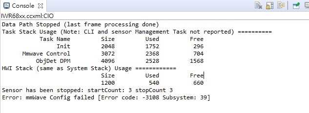
    error message:

    Data Path Stopped (last frame processing done)
    Task Stack Usage (Note: CLI and sensor Management Task not reported) ==========
    Task Name Size Used Free
    Init 2048 1752 296
    Mmwave Control 3072 2368 704
    ObjDet DPM 4096 2528 1568
    HWI Stack (same as System Stack) Usage ============
    Size Used Free
    1200 540 660
    Sensor has been stopped: startCount: 3 stopCount 3
    Error: mmWave Config failed [Error code: -3108 Subsystem: 39]

  • sorry!  

    about : error message:

    After copying and pasting. Some problems
    So i attach the picture.

  • Your new profile has changed the ADC rate from 2400 to 1200.   The lowest ADC rate is 2000.

    Best,

    Zigang

  • Hi Zigang,

    about the Idle Time, ADC Valid Start Time, excess ramping time , slop ,  Are there similar restrictions?

    Thanks!

    Ping

  • Hi, 

    Some of the limitations are listed in the SDK doxygen documentation located at:

    file:///C:/ti/mmwave_sdk_03_03_00_03/packages/ti/control/mmwavelink/docs/doxygen/html/structrl_profile_cfg__t.html

    For the limitation of idle time, ADC valid start time, excess ramping time, there is another app notes located at:

    http://www.ti.com/lit/an/swra553a/swra553a.pdf

    Best,

    Zigang