This thread has been locked.

If you have a related question, please click the "Ask a related question" button in the top right corner. The newly created question will be automatically linked to this question.

CCS/PGA460-Q1: Problem with UMR Command. MSB value locked at 0x41. Maximum distance measured 5.61m.

Part Number: PGA460-Q1
Other Parts Discussed in Thread: PGA460, BOOSTXL-PGA460

Tool/software: Code Composer Studio

Dear coleagues,

Actually I'm work with a PGA460 applied in a industrial ultrasonic sensor and I don't know why I can not measure more them 5.61 (half of maximum PGA distance in a normal application). When I use a UMR Command and MSB value are locked at 0x41 and LSB changes correctaly.


I'm use a 80khz transducer and want detect up to 8m.

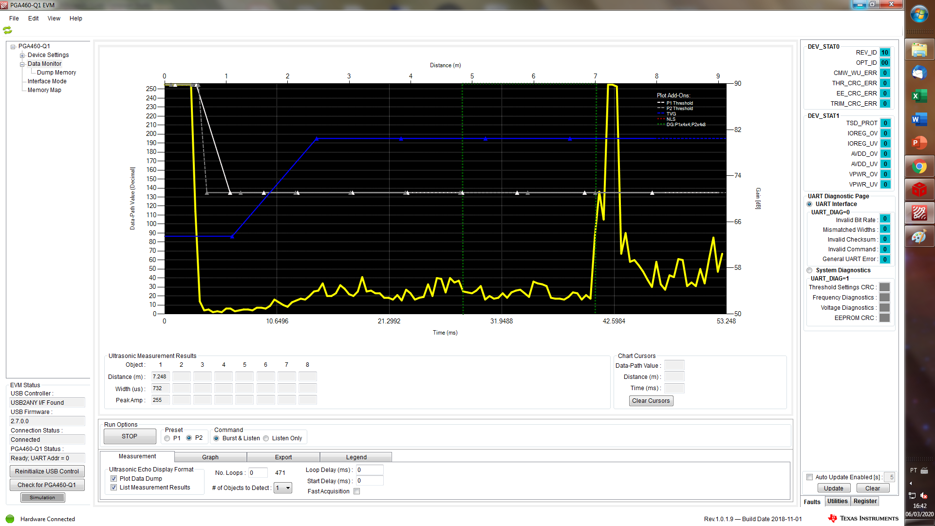
Below my memory data and part of code used to transmit.

#define P1BL            0x00    // Burst and Listen (Preset 1)
#define P2BL            0x01    // Burst and Listen (Preset 2)
#define P1LO            0x02    // Listen Only (Preset 1)
#define P2LO            0x03    // Listen Only (Preset 2)
#define TNLM            0x04    // Temperature and Noise-level measurement
#define UMR             0x05    // Ultrasonic Measurement Result
#define TNLR            0x06    // Temperature and noise level result
#define TEDD            0x07    // Transducer echo data dump
#define SD              0x08    // System diagnostics
#define SRR             0x09    // Register read
#define SRW             0x0A    // Register write
#define EEBR            0x0B    // EEPROM bulk read
#define EEBW            0x0C    // EEPROM bulk write
#define TVGBR           0x0D    // Time-varying-gain bulk read
#define TVGBW           0x0E    // Time-varying-gain bulk write
#define THRBR           0x0F    // Threshold bulk read
#define THRBW           0x10    // Threshold bulk write

// Broadcast -- device will execute command irrespecive of UART address field
#define BC_P1BL         0x11    // Burst and listen (Preset 1)
#define BC_P2BL         0x12    // Burst and listen (Preset 2)
#define BC_P1LO         0x13    // Listen only (Preset 1)
#define BC_P2LO         0x14    // Listen only (Preset 2)
#define BC_TNLM         0x15    // Temperature and noise-level measurement
#define BC_SRW          0x16    // Register write
#define BC_EEBW         0x17    // EEPROM bulk write
#define BC_TVGBW        0x18    // Time varying-gain bulk write
#define BC_THRBW        0x19    // Threshold bulk write

// Addresses and Settings
#define EE_CNTRL_ADDR   0x40
#define EE_UNLOCK_ST1   0x68
#define EE_UNLOCK_ST2   0x69

// EEPROM -- non-volatile
#define USER_DATA1      0x0    //reg addr       0x0
#define USER_DATA2      0x0     //reg addr      0x1
#define USER_DATA3      0x0     //reg addr      0x2
#define USER_DATA4      0x0     //reg addr      0x3
#define USER_DATA5      0x0     //reg addr      0x4
#define USER_DATA6      0x0     //reg addr      0x5
#define USER_DATA7      0x0     //reg addr      0x6
#define USER_DATA8      0x0     //reg addr      0x7
#define USER_DATA9      0x0     //reg addr      0x8
#define USER_DATA10     0x0     //reg addr      0x9
#define USER_DATA11     0x0     //reg addr      0x0A
#define USER_DATA12     0x0     //reg addr      0x0B
#define USER_DATA13     0x0     //reg addr      0x0C
#define USER_DATA14     0x0     //reg addr      0x0D
#define USER_DATA15     0x0     //reg addr      0x0E
#define USER_DATA16     0x0     //reg addr      0x0F
#define USER_DATA17     0x0     //reg addr      0x10
#define USER_DATA18     0x0     //reg addr      0x11
#define USER_DATA19     0x0     //reg addr      0x12
#define USER_DATA20     0x0     //reg addr      0x13
#define TVGAIN0         0xEE    //reg addr      0x14
#define TVGAIN1         0xFF    //reg addr      0x15
#define TVGAIN2         0xFF    //reg addr      0x16
#define TVGAIN3         0xB2    //reg addr      0x17
#define TVGAIN4         0xCB    //reg addr      0x18
#define TVGAIN5         0x2C    //reg addr      0x19
#define TVGAIN6         0xB0    //reg addr      0x1A
#define INIT_GAIN       0x4A    //reg addr      0x1B
#define FREQUENCY       0xFA    //reg addr      0x1C
#define DEADTIME        0xFF    //reg addr      0x1D
#define PULSE_P1        0x3F    //reg addr      0x1E
#define PULSE_P2        0x1F    //reg addr      0x1F
#define CURR_LIM_P1     0x3F    //reg addr      0x20
#define CURR_LIM_P2     0x7F    //reg addr      0x21
#define REC_LENGTH      0x3C    //reg addr      0x22
#define FREQ_DIAG       0x21    //reg addr      0x23
#define SAT_FDIAG_TH    0x22    //reg addr      0x24
#define FVOLT_DEC       0x69    //reg addr      0x25
#define DECPL_TEMP      0x0F    //reg addr      0x26
#define DSP_SCALE       0x00     //reg addr     0x27
#define TEMP_TRIM       0x0     //reg addr      0x28
#define P1_GAIN_CTRL    0x12     //reg addr     0x29
#define P2_GAIN_CTRL    0xDA     //reg addr     0x2A

#define EE_CRC          0xDB    //reg addr      0x2B

// Register-based -- volatile
#define EE_CNTRL        0x0     //reg addr      0x40

#define BPF_A2_MSB      0x91    //reg addr      0x41
#define BPF_A2_LSB      0x3A    //reg addr      0x42
#define BPF_A3_MSB      0xF9    //reg addr      0x43
#define BPF_A3_LSB      0xA5    //reg addr      0x44
#define BPF_B1_MSB      0x03     //reg addr      0x45
#define BPF_B1_LSB      0x2D    //reg addr      0x46
#define LPF_A2_MSB      0x7E    //reg addr      0x47
#define LPF_A2_LSB      0x67    //reg addr      0x48
#define LPF_B1_MSB      0x00     //reg addr      0x49
#define LPF_B1_LSB      0xCD    //reg addr      0x4A

#define TEST_MUX        0xCD     //reg addr      0x4B
#define DEV_STAT0       0x80    //reg addr      0x4C
#define DEV_STAT1       0x0     //reg addr      0x4D

// Register-based -- volatile


#define P1_THR_0        0x69    //reg addr      0x5F
#define P1_THR_1        0xBB    //reg addr      0x60
#define P1_THR_2        0xBD    //reg addr      0x61
#define P1_THR_3        0xDD    //reg addr      0x62
#define P1_THR_4        0xDE     //reg addr      0x63
#define P1_THR_5        0xEE    //reg addr      0x64
#define P1_THR_6        0xFF    //reg addr      0x65
#define P1_THR_7        0xE1    //reg addr      0x66
#define P1_THR_8        0x08    //reg addr      0x67
#define P1_THR_9        0x42    //reg addr      0x68
#define P1_THR_10       0x10    //reg addr      0x69

#define P1_THR_11       0x87    //reg addr      0x6A
#define P1_THR_12       0x87    //reg addr      0x6B
#define P1_THR_13       0x87    //reg addr      0x6C
#define P1_THR_14       0x87    //reg addr      0x6D
#define P1_THR_15       0x07     //reg addr      0x6E

#define P2_THR_0        0x49    //reg addr      0x6F
#define P2_THR_1        0x45    //reg addr      0x70
#define P2_THR_2        0xBD    //reg addr      0x71
#define P2_THR_3        0xDD    //reg addr      0x72
#define P2_THR_4        0xDE    //reg addr      0x73
#define P2_THR_5        0xEE    //reg addr      0x74
#define P2_THR_6        0xFF    //reg addr      0x75
#define P2_THR_7        0xFF    //reg addr      0x76
#define P2_THR_8        0x08    //reg addr      0x77
#define P2_THR_9        0x42    //reg addr      0x78
#define P2_THR_10       0x10    //reg addr      0x79
#define P2_THR_11       0x87    //reg addr      0x7A
#define P2_THR_12       0x87    //reg addr      0x7B
#define P2_THR_13       0x87    //reg addr      0x7C
#define P2_THR_14       0x87    //reg addr      0x7D
#define P2_THR_15       0x07     //reg addr      0x7E
#define THR_CRC         0xE4    //reg addr      0x7F


I have been change these values using a Texas Board with PGA460-Q1 EVM. When I saw a consistent signal I made a copy to these data to use in my proprietary hardware.
Using a datamonitor I sow a good signal to 8m or more.

In my proprietary board, until 5.61 meter works very well but MSB dont change. I don't believe in hardware problems ou poor signal. I wait 60ms to each burst and listen.

Part of code:
if ((getTime_ms() - lastexection) >= 60)// roda a cada 60ms quando selecionado modo 0
        {
            uint8_t buf_tx[4] = {SYNCBYTE, MODE_LONG_RANGE, 0x01, 0xFF};
            uint8_t checksum = calc_checksum4(&buf_tx[1], 2);
            buf_tx[3] = checksum;
            unsigned char n=0;
            for(n=0;n<4;n++)
            {
                EUSCI_A_UART_transmitData(EUSCI_A0_BASE, buf_tx[n]);// gero pulso para transmissão
            }
            GPIO_toggleOutputOnPin(GPIO_PORT_P1,GPIO_PIN6);// led verde
            lastexection = getTime_ms();      // get the current time
            request_results();
            MSB=buf_distancia[1];
            LSB=buf_distancia[2];
            LOBULO=buf_distancia[3];
            AMPLITUDE=buf_distancia[4];
        }
        //request_results();
        //MSB=buf_distancia[1];
        //LSB=buf_distancia[2];
        //LOBULO=buf_distancia[3];
        //AMPLITUDE=buf_distancia[4];
        plobulo=LOBULO*100/255;
        pamplitute = AMPLITUDE*100/255;
        //distancia = ((343/2)*(((MSB<<8)+LSB)*0.000001))+((343/2)*(31*(1/80000))); // formula sem compensação da variação da temperatura
        distancia = (((331/2)+0.3*tempok)*(((MSB<<8)+LSB)*0.000001))+(((331/2)+0.3*tempok)*(31*(1/80000))); // formula com compensação da variação da temperatura

What am I doing wrong?

Thanks for all your help!

Reinaldo Borsato

  • Hi Reinaldo,

    Can you plot the echo data dump data (command 7; ensure DATADUMP_EN = 1) after your burst/listen command to see what your envelope looks like? This will help to determine if the threshold is mapped correctly to the envelope; otherwise, an incorrect threshold mapping may result in the wrong ultrasonic measurement result.

    Also, confirm the following:

    • You are writing to the threshold at least once after power-up/cycle and before the burst/listen command to clear the THR_CRC_ERR to '0'.
    • You are not mistaking the diagnostic field for the ultrasonic measurement results's MSB. Remember, every response command's first byte is the UART Diagnostic Data byte, which should be a value of 0x40 if there was no UART error. Considering your value is always 0x41, it almost looks like UART Diagnostic Data byte with the "device busy flag" set.
    • Ensure you wait a sufficient amount of time between the time the burst/listen command is sent to when you read back the ultrasonic measurement results. It looks like you have added a 60ms delay function in your code, but just verify you are waiting for the preset 1 or 2 record length time to expire before reading the ultrasonic measurement results.

  • Hi Akeem, 

    Well, until now I''m dont use command 7, only command 5 to acquire a distance.
    The image below was taken using a Texas Board BOOSTXL-PGA460 and I can detect my target without problems.

    About "You are writing to the threshold at least once after power-up/cycle and before the burst/listen command to clear the THR_CRC_ERR to '0'.":

    Everytime when I turnon the sensor the thresholds are updated and EEprom are write only if that was not made before. See part of the code below. 

    void inicia_pga(void)//run once before main
    {
    
            const uint8_t array_size = 35;// inicialização dos thresholds
                  uint8_t settings_buf[35] = {SYNCBYTE, BC_THRBW,
                                P1_THR_0, P1_THR_1, P1_THR_2, P1_THR_3, P1_THR_4, P1_THR_5,
                                P1_THR_6, P1_THR_7, P1_THR_8, P1_THR_9, P1_THR_10,
                                P1_THR_11, P1_THR_12, P1_THR_13, P1_THR_14, P1_THR_15,
                                P2_THR_0, P2_THR_1, P2_THR_2, P2_THR_3, P2_THR_4, P2_THR_5,
                                P2_THR_6, P2_THR_7, P2_THR_8, P2_THR_9, P2_THR_10,
                                P2_THR_11, P2_THR_12, P2_THR_13, P2_THR_14, P2_THR_15, 0xFF
                               };
    
                  uint8_t checksum = calc_checksum(&settings_buf[1], sizeof(settings_buf) - 2);
                  settings_buf[array_size - 1] = checksum;
                  unsigned char n=0;
                  for(n=0;n<array_size;n++)
                  {
                  EUSCI_A_UART_transmitData(EUSCI_A0_BASE, settings_buf[n]);
                  }
                  __delay_cycles(10000);// Must wait >50us per datasheet
                  read_eeprom();
    
    }
    
    void read_eeprom(void)
    {
        unlock_eeprom();
        //__delay_cycles(10000);
        uint8_t buf_tx[2] =  {SYNCBYTE, EEBR};//era THRBR = leitura dos threshold (32 posições vetor de leitura) foi para leitura eeprom43 posicoes vetor
                   unsigned char nx=0;
                                 for(nx=0;nx<2;nx++)
                                 {
                                 EUSCI_A_UART_transmitData(EUSCI_A0_BASE, buf_tx[nx]);
                                 }
                                 __delay_cycles(10000); // inserido posteriormente para tentar solucionar problema 12/02
    // valores lidos na interrupção
                                 if(EE_CRC==checksum)
                                 {
                                     __delay_cycles(10000);
                                     flag_gravaE2prom =0;
    
                                                 // write_eeprom();
                                                  //__delay_cycles(1000);
                                 }
                                 else
                                 {
                                     __delay_cycles(10000); // inserido posteriormente para tentar solucionar problema 12/02
                                     flag_gravaE2prom =1;
                                     write_eeprom();
                                     __delay_cycles(10000);
                                 }
    }
    
    void unlock_eeprom(void)
    {
        uint8_t eeprom_write_buf[5] = {SYNCBYTE, SRW, EE_CNTRL_ADDR, EE_UNLOCK_ST1, 0xFF};
                   checksum = calc_checksum5(&eeprom_write_buf[1], sizeof(eeprom_write_buf) - 2);
                   eeprom_write_buf[4] = checksum;
                   unsigned char n0=0;
                                         for(n0=0;n0<5;n0++)
                                         {
                                         EUSCI_A_UART_transmitData(EUSCI_A0_BASE, eeprom_write_buf[n0]);
                                         }
    }


    void write_eeprom(void)
    {
    
        uint8_t buf_tx[46] =  {SYNCBYTE, EEBW, USER_DATA1, USER_DATA2, USER_DATA3, USER_DATA4,
                               USER_DATA5, USER_DATA6, USER_DATA7, USER_DATA8, USER_DATA9, USER_DATA10,
                               USER_DATA11, USER_DATA12, USER_DATA13, USER_DATA14, USER_DATA15, USER_DATA16,
                               USER_DATA17, USER_DATA18, USER_DATA19, USER_DATA20,
                               TVGAIN0, TVGAIN1, TVGAIN2, TVGAIN3, TVGAIN4, TVGAIN5, TVGAIN6, INIT_GAIN, FREQUENCY, DEADTIME,
                               PULSE_P1, PULSE_P2, CURR_LIM_P1, CURR_LIM_P2, REC_LENGTH, FREQ_DIAG, SAT_FDIAG_TH, FVOLT_DEC, DECPL_TEMP,
                               DSP_SCALE, TEMP_TRIM, P1_GAIN_CTRL, P2_GAIN_CTRL, 0xFF};
    
        uint8_t checksum = calc_checksum46(&buf_tx[1], sizeof(buf_tx) - 2);
        buf_tx[45] = checksum;
    
        unsigned char n=0;
                              for(n=0;n<46;n++)
                              {
                              EUSCI_A_UART_transmitData(EUSCI_A0_BASE, buf_tx[n]);
                              }
                              __delay_cycles(10000);
                              unlock_eeprom();
                              __delay_cycles(10000);
                              flash_eeprom();
    }
    
    
    void flash_eeprom(void)
    {
        uint8_t eeprom_write_buf[5] = {SYNCBYTE, SRW, EE_CNTRL_ADDR, EE_UNLOCK_ST2, 0xFF};
            uint8_t checksum = calc_checksum5(&eeprom_write_buf[1], sizeof(eeprom_write_buf) - 2);// talvez chamada errada. correco calc_checksum5 era callcheksum
            eeprom_write_buf[4] = checksum;
            unsigned char n=0;
                                      for(n=0;n<5;n++)
                                      {
                                      EUSCI_A_UART_transmitData(EUSCI_A0_BASE, eeprom_write_buf[n]);
                                      }
    }

    About: "You are not mistaking the diagnostic field for the ultrasonic measurement results's MSB. Remember, every response command's first byte is the UART Diagnostic Data byte, which should be a value of 0x40 if there was no UART error. Considering your value is always 0x41, it almost looks like UART Diagnostic Data byte with the "device busy flag" set."

    The code to transmit data that I use is very simple. After the transmition I receive de data in a Uart Interrupt and calculate a distance using the value to each position in a buffer.

    void request_results(void)
    {
        //flag_temp_noise=0; // teste
        uint8_t buf_tx[2] =  {SYNCBYTE, UMR};
                       unsigned char nx=0;
                                     for(nx=0;nx<2;nx++)
                                     {
                                     EUSCI_A_UART_transmitData(EUSCI_A0_BASE, buf_tx[nx]);
                                     }
                                     ndist =0;
    }
    
    // part to receive in a interrupt
    void EUSCI_A0_ISR(void)
            {
                switch(__even_in_range(UCA0IV,USCI_UART_UCTXCPTIFG))
                {
                    case USCI_NONE: break;
                    case USCI_UART_UCRXIFG:
    
                        //if((n1<=sizeof(buf_rx)&&(flag_gravaE2prom == 1 ))
                        if(n1<=sizeof(buf_rx)&&(flag_gravaE2prom == 1 ))
                        {
                            buf_rx[n1]=EUSCI_A_UART_receiveData(EUSCI_A0_BASE);
                            n1++;
                        }
                        else// garanto que a eeprom já foi gravada ao menos uma vez e inicio a tratativa da RX
                        {
                            n1=0;
                            flag_gravaE2prom = 0;
    
    
                            if(ndist<=sizeof(buf_distancia))
                            {
                                buf_distancia[ndist]=EUSCI_A_UART_receiveData(EUSCI_A0_BASE);
                                ndist++;
    
                            }
                            else
                            {
                                ndist=0;
                            }
                        }
                        break;
                   case USCI_UART_UCTXIFG: break;
                   case USCI_UART_UCSTTIFG: break;
                   case USCI_UART_UCTXCPTIFG: break;
                }
    

    About: "Ensure you wait a sufficient amount of time between the time the burst/listen command is sent to when you read back the ultrasonic measurement results. It looks like you have added a 60ms delay function in your code, but just verify you are waiting for the preset 1 or 2 record length time to expire before reading the ultrasonic measurement results."

    I'm wait 60ms to each burst and listen to execute a function request_results(); (function to transmit sync e UMR above).
    The answer stay in my buffer (interrupt) and I only read the value to each 60ms too.
    Next week I'LL check the timers again...

    Best Regards!

    Reinaldo

  • Hi Akeem,


    I would like to thank you. You are right about the 0x41. I saw a byte 0, not a byte 1.

    After check again the MSB and LSB registers I saw that PGA worked well (in my proprietary PCB). See my data below:

    Target distance MSB LSB
    1m 0x17 0x31
    2m 0x2C 0xDC
    3m 0x43 0xA9
    4m 0xBA 0XCD
    5m 0X71 0xBE
    5,6m 01111101 01000000
    6m(stop to calculate) 10000110 00001110

    After my most significant bit are set my software are calculate wrong the distance. I'LL verify my variables but a problem is here:

    distancia = (((331/2)+0.3*tempok)*(((MSB<<8)+LSB)*0.000001))+(((331/2)+0.3*tempok)*(31*(1/80000))); // formula com compensação da variação da temperatura

    The variable tempok is the temperature in C°.

    Best Regards,

    Reinaldo