


Hi,
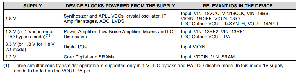
1. How to use VOUT_PA when VIN_13RF is 1V? In the schematic diagram, 1V voltage is fed into VOUT_PA.
2. When VIN_13RF is 1.3v, can the three-way transmission channel of AWR1843 work in time?According to the official website information, what I understand is that under the 1V power supply mode, it can guarantee the simultaneous operation of three transmitting channels.
The 3-way chip should still work when the power supply is 1.3v.It's just that you can't launch all three at once. It's possible if we use three.
3. At present, our circuit design refers to the schematic diagram of the official website.VIN_13RF is 1V, and 1V is supplied to VOUT_PA, but the chip cannot be started at present, only the program can be burned.
However, when the program runs in the waveform output, it will be directly interrupted.All voltage measurements are normal. It is not clear why the chip does not work when 1V is supplied.
Thanks!
