This thread has been locked.

If you have a related question, please click the "Ask a related question" button in the top right corner. The newly created question will be automatically linked to this question.

LDC1000: Turning of magnetic encoder influences proximity signal

Part Number: LDC1000

Hello, 

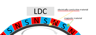
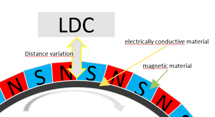
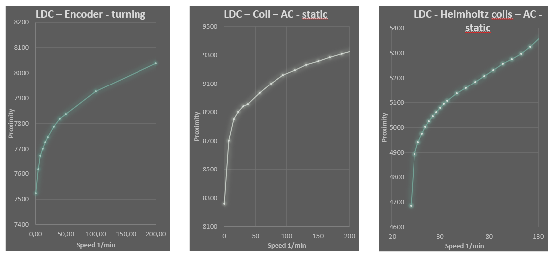
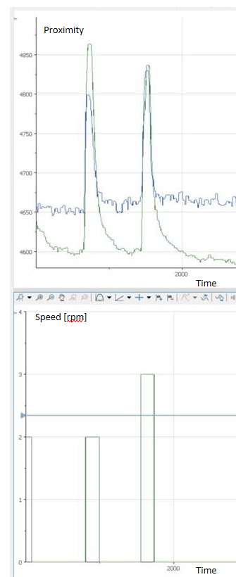
we see following effect when our magnetic Encoder ring starts turning. Can you explain this behaviour?

I expect same behaviour will occur when switching to the successor chip LDC1001?

Thanks in advance. 

Regards

Frank

  • Hi Frank,

    Thank you for posting the question. Give us a couple of days to get back to you while we review your request. Thanks. 

  • Hello Arjun,

    thanks for your Response. In addition I insert a picture which shows the setup.

    Thanks.

    Regards

    Frank

  • Frank,

    Anything you are observing with LDC1000 will likely be observed also on LDC1001.

    I would like to be sure I am following your plots correctly.  It appears that you are stepping through discrete rotational speeds of the magnet and this is triggering a position change for the inductive sensor.  Does the speed have any impact on the response from LDC1000?

    I would like to understand your configuration a little better as well.  You are mixing inductive sensing and hall sensing?  How is the inductive target moving relative to the sensor? What are the shape and material of the inductive target?  Does it move simultaneous or independent to the magnetic material?  How many poles does your magnet have? Can you help us understand the application a little more?

    We have seen in the past that sometimes a few different things might actually impact the sensor.  If the magnetic material is conductive enough, it may actually present as a target when placed close to the sensor.  Also, any capacitive coupling effect from any source may force a change in resonant frequency of the LC tank and result in a perceived change in position.  

    Thanks,

    Scott

  • I would like to be sure I am following your plots correctly.  It appears that you are stepping through discrete rotational speeds of the magnet and this is triggering a position change for the inductive sensor.  Does the speed have any impact on the response from LDC1000?

    ==> With a constant distance to the magnetic encoder, the change of the proximity value is greatest when starting the rotary movement. With increasing speed this influence decreases. It appears as if there is an offset of the proximity signal that increases with the speed.


    I would like to understand your configuration a little better as well.  You are mixing inductive sensing and hall sensing?
    ==> We use one target - consisting of an electrically conductive carrier ring and a magnetised layer - for 2 sensors.


     How is the inductive target moving relative to the sensor?
    ==> Please see Picture.


    What are the shape and material of the inductive target? 
    ==> ringshaped

     Does it move simultaneous or independent to the magnetic material? 
    ==> As the inductive target and the magnetic material is one machine part the movements can’t be independent, but the inductive measurement can take place with or without turning of the magnetic material.

     How many poles does your magnet have? Can you help us understand the application a little more?
    ==> The magnet has 32 pol pairs.

    We have seen in the past that sometimes a few different things might actually impact the sensor.  If the magnetic material is conductive enough, it may actually present as a target when placed close to the sensor.  Also, any capacitive coupling effect from any source may force a change in resonant frequency of the LC tank and result in a perceived change in position.  
    ==> We checked with same LDC setup also the behaviour with AC-magnetic fields generated by coils and saw similar effects. The first picture shows the LDC with the turning magnetic encoder, the second picture shows the LDC with a coil supplied with an AC-current with different frequencies and the third one shows the LDC placed in a Helmholtz coil exposed an AC magnetic field.  


    Thanks,
    ==> Frank

  • Frank,

    Thank you for these details. 

    It appears that you are creating enough AC magnetic field based on the rotation of your target to interfere with the sensor.  Could you provide details of your sensor LC values?  If the resonant frequency is set low enough, it might be possible this we are impacting the passband of the sensor.  You could try changing your sensor C value to see what impact this has on your results.  As you do, however, make sure that you stay within the valid sensor Rp and frequency ranges as defined in the electrical characteristics table of the datasheet.  We typically recommend operating in the upper kHz to lower MHz for the best measurement resolution.

    Another thought is related to the material and geometry of the conductive ring.  I'm curious if it is possible that the magnet impacts the ability to consistently generate eddy currents in the ring as it rotates.  Could you also provide details regarding the sensor geometry as well?