Hi,
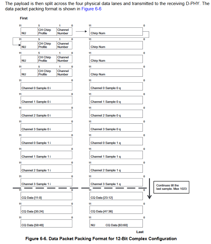
as asked in the last thread, I would like to know, in which manner data are in the buffer. Today as i was looking at the technical user guide for the IWR, I found this: I believe it answers my questions in a way however not fully. As i understand,
1. The data is place in memory from left to right, then left again. I would be like this
Channel 0 sample 0 i -> Channel 0 sample 0 q-> channel 1 sample 0 i->channel 1 sample 0 i. My buffer data is therefore also like this.
I am correct in my assumption?
2. I don't need the first 8 data packets, if i only want the data. ?
Is this also correct.?
The datastructure in the bufer would be N


