This thread has been locked.

If you have a related question, please click the "Ask a related question" button in the top right corner. The newly created question will be automatically linked to this question.

CCS/IWR1443: DCA1000EVM: IWR1443, Read the raw data for BPM mode using 2Tx and 4Rx antennas

Part Number: IWR1443

Tool/software: Code Composer Studio

Hi,

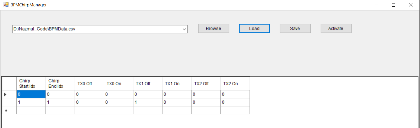
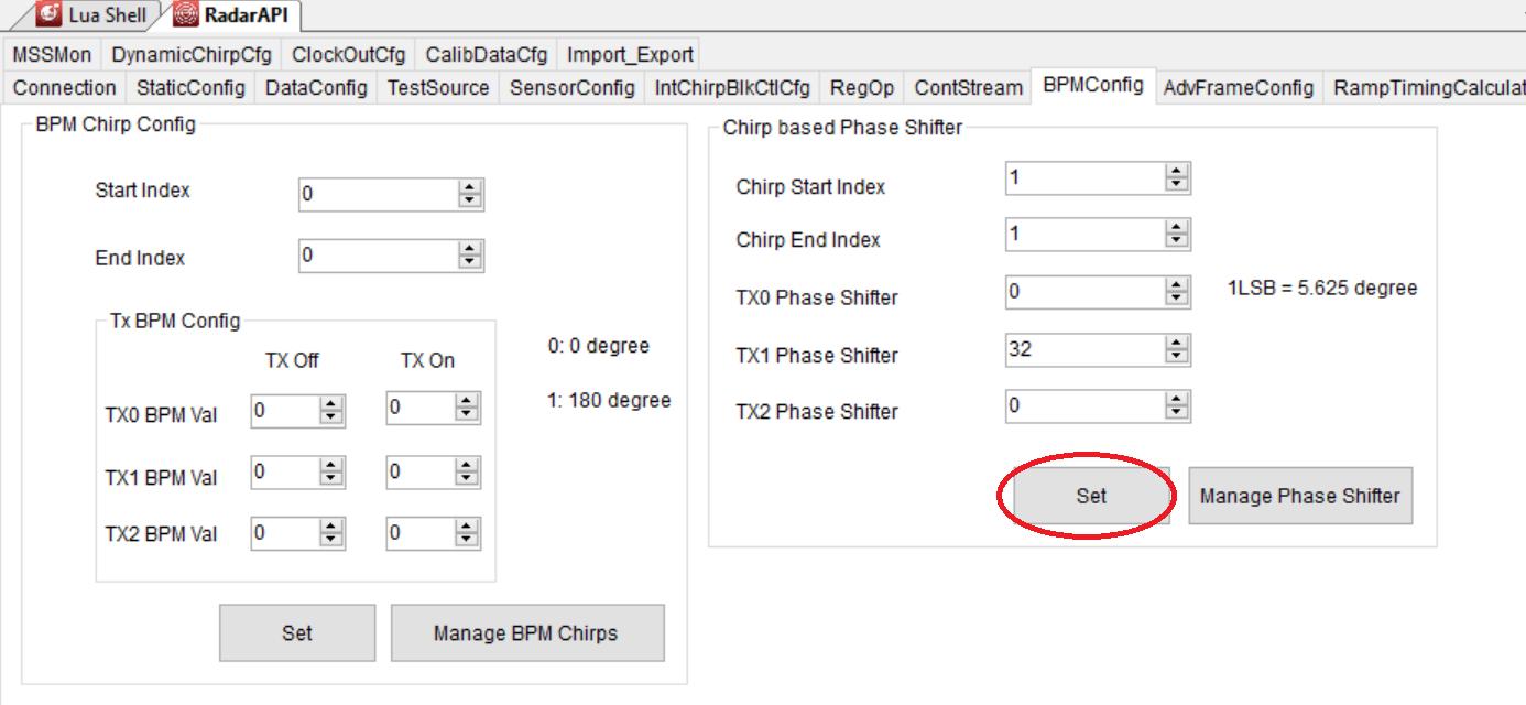
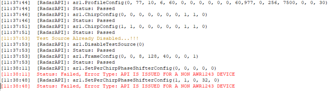
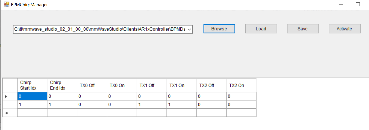
I recorded the data with BPM mode. I used Tx0 and Tx1 to record the data. To record the data I used the Settings below for mmstudio.

%% parameters
samples = 256;
chirps = 128;
channels = 4;
numTX = 2;
frames = 8;
Slope = 60.977e12; %MHz/us
samplingRate = 7.5e6;
rampEnd = 60e-6;
frequency = 77e9;

To read the data I used the matlab code  below.

%%% DCA1000 With xWR12xx and xWR14xx MATLAB Example
%%% This script is used to read the binary file produced by the DCA1000
%%% and Mmwave Studio
%%% Command to run in Matlab GUI - readDCA1000('<ADC capture bin file>')
%% global variables
% change based on sensor config
numADCBits = 16; % number of ADC bits per sample
numLanes = 4; % do not change. number of lanes is always 4 even if only 1 lane is used. unused lanes
isReal = 0; % set to 1 if real only data, 0 if complex data are populated with 0
%% read file and convert to signed number
% read .bin file
fid = fopen("D:\\Data\\IWR1443\\adc_data_BPM_MIMO_1443.bin",'r'); % D:\Data\adc_data(IWR1443).bin
% DCA1000 should read in two's complement data
adcData = fread(fid, 'int16');
% if 12 or 14 bits ADC per sample compensate for sign extension
if numADCBits ~= 16
 l_max = 2^(numADCBits-1)-1;
 adcData(adcData > l_max) = adcData(adcData > l_max) - 2^numADCBits;
end
fclose(fid);
%% organize data by LVDS lane
% for real only data
if isReal
 % reshape data based on one samples per LVDS lane
 adcData = reshape(adcData, numLanes, []);
%for complex data
else
 % reshape and combine real and imaginary parts of complex number
 adcData = reshape(adcData, numLanes*2, []);
 adcData = adcData([1,2,3,4],:) + sqrt(-1)*adcData([5,6,7,8],:);
end

%% rearrange data according to transmitter

radar_data = reshape(adcData, 4, 256, 128, 8);   %reshape(adcData, channels, samples, chirps, frames);
Sa = radar_data(:,:,1:2:end,:);
Sb = radar_data(:,:,2:2:end,:);
Tx0 = (Sa + Sb)/2;
Tx1 = (Sa - Sb)/2;
radar_data_combined = vertcat(Tx0, Tx1);
radar_data_combined = permute(radar_data_combined,[2,3,1,4]);  %(samples, chirps, channels, frames)
I added the last Portion of the Code.
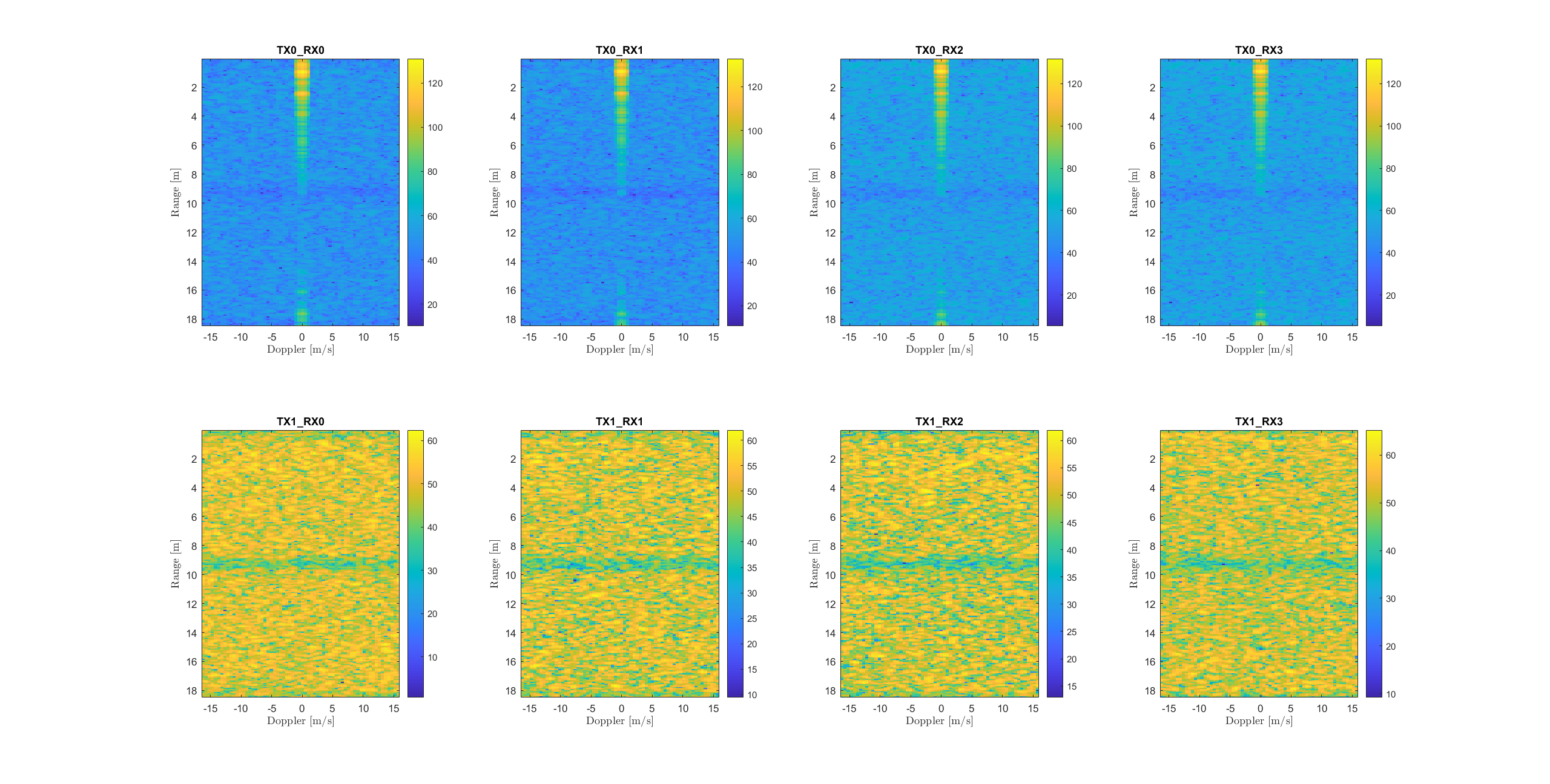
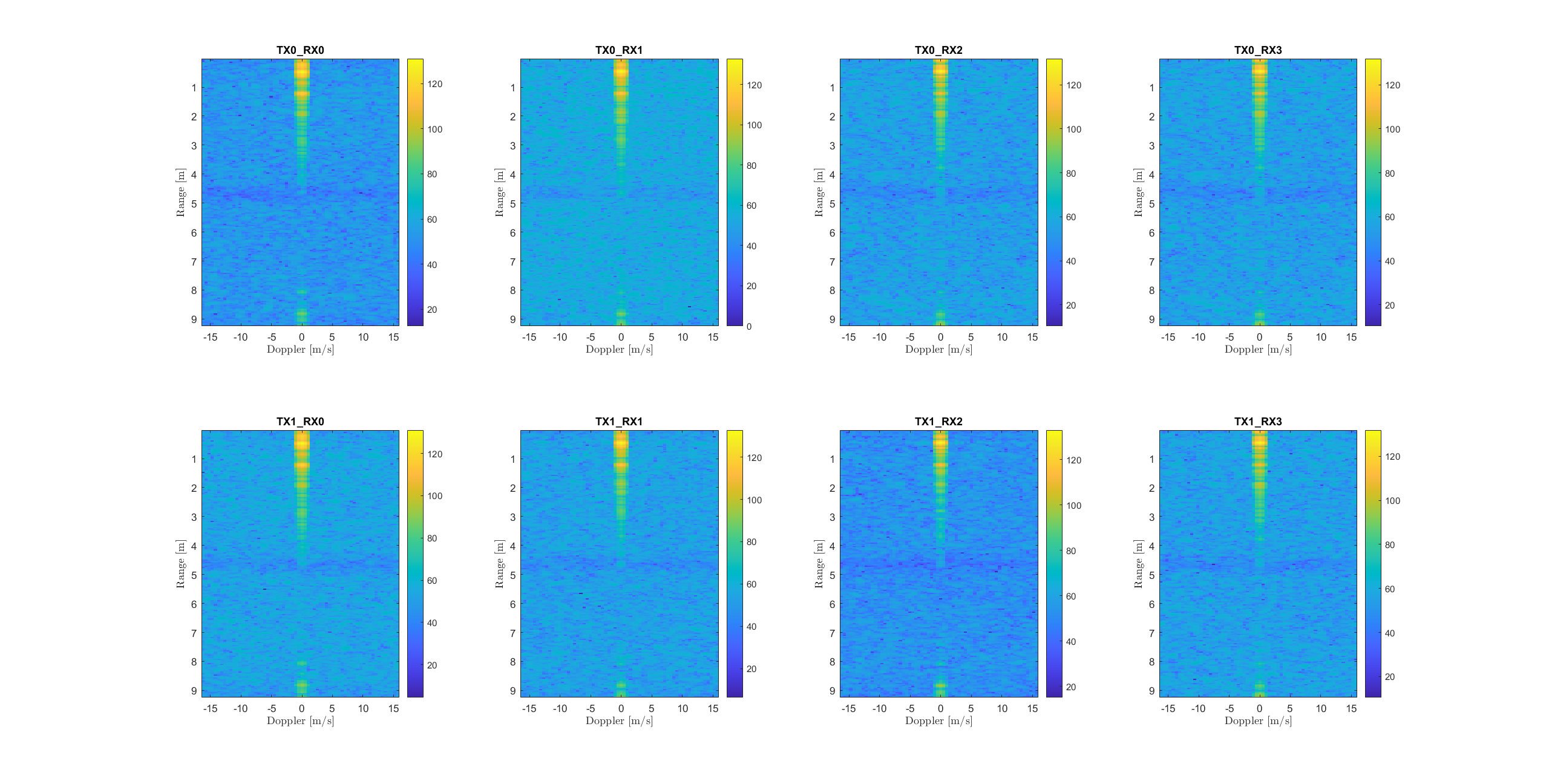
I want to rearrange my data like this way, (TX0_Rx0, TX0_Rx1, TX0_Rx2, TX0_Rx3, TX1_Rx0,TX1_Rx1, TX1_Rx2, TX1_Rx3), like 8 virtual channels.
My question is, Is this the right way to read the raw data?
regards,
Nazmul

  • HI, Nazmul:

    Sorry we can not review code for the customer.  But the code that how you calculate TX0 and TX1 looks right to me.   To help debug the code, you can verify through plotting the ADC data (of the same antenna pair) for different chirp and see whether they are on top of each other.   

    radar_data = reshape(adcData, 4, 256, 128, 8);   %reshape(adcData, channels, samples, chirps, frames);
    Sa = radar_data(:,:,1:2:end,:);
    Sb = radar_data(:,:,2:2:end,:);
    Tx0 = (Sa + Sb)/2;
    Tx1 = (Sa - Sb)/2;
    Best,
    Zigang
  • Hi Zigang,

    Thank you for your reply.

    I did the R-D spectrum for each pair of antennas for the BPD configured data. The Problem is it seems it is not showing correct result. Thats how i suspected that there might have some Problems for reading data.

     This is generated for the BPM configured data. For Tx1 it is not showing correct as Tx0.

    I have done with the TDM configured data and it seems it works fine.

    The Code for reading TDM data is below,

    radar_data = reshape(adcData, 4, 256, 128, 8);   %reshape(adcData, channels, samples, chirps, frames);
    Tx0 = radar_data(:,:,1:2:end,:);
    Tx1 = radar_data(:,:,2:2:end,:);
    radar_data_combined = vertcat(Tx0, Tx1);
    radar_data_combined = permute(radar_data_combined,[2,3,1,4]);
    And the R-D spectrum looks fine for TDM.
    Where is the mistake?
  • How did you configure the profile and chirps to achieve BPM MIMO?

    Best,

    Zigang

  • Hi,

    Here is the configuration.

  • HI, 

    This BPM configuration looks very confusing to me.  Can you use the "chirp based phase shifter" in the same tab ? 

    By the way, why you only have one chirp?  I think you will need to have two chirp, one for TX1 + TX2, and one chirp for TX1-TX2.  And your frame configuration should  have start Chirp 0 and end chirp 1, right?

    Best,

    Zigang

  • Hi Zigang,

    Yes, you are right, but the Question is how to do it un this mmstudio. The steps are:

    Sensor Config Tab:

    1. Profile Configuration: I setup a profile with id 0.
    2. In chirp configuration : I configured only one chirp with the above profile id 0. Question is, Do I need to configure 2 chirps with id 0 and 1 with the same Profile configuration 0? I have tried it but it does not work for the same profile id 0. I have to set 2 profile with 0 and 1.
    3. Frame COnfiguration: Here I set Start chirp 1 and end chirp 2, which makes sence.

    BPM Configuration tab: What to do here, Can you please tell me in details. Which one to configure, BPM Chirp Config or the Chirp based phase shifter? I read about BPM theory from documentation but no where it is mentioned how to set up the BPM in mmwave studio. It is more about the User Interface.

    regards,

    Nazmul

  • HI, Nazmul:

    You should not have problem configure different chirp with same profile configuration.  You can do:

    ar1.ChirpConfig(0, 0, 0, 0, 0, 0, 0, 1, 0, 1)

    ar1.ChirpConfig(1, 1, 0, 0, 0, 0, 0, 1, 0, 1)

    ar1.FrameConfig(0, 1, 8, 64, 40, 0, 0, 1)

    Assume you will use TX1 and TX3 to do BPM.

    And then program the phase shifter for chirp0 and chirp1 as below:

    ar1.SetPerChirpPhaseShifterConfig(0, 0, 0, 0, 0)

    ar1.SetPerChirpPhaseShifterConfig(1, 1, 0, 32, 0)

    THis command can be programmed in the BPMConfig tab as below:

    Best,

    Zigang

  • Hello,

    I have activated Tx0 and Tx1. Then I tried to follow you. The BPM configuration does not work.

    I am using IWR1443. Why this error message is generating?

    Best regards,

    Nazmul

  • HI, Nazmul:

    Which radar studio version you are using and which BSS/MSS firmware you are loading?   Which version is your xwr1443 device.   I do not have this problem.   By the way, your frameCfg is still have one chirp instead of two.

    Best,

    Zigang

  • Hi Zigang,

    I am using mm Studio 2.1.0.0. The BSS and MSS files are located,

    C:\ti\mmwave_studio_02_01_00_00\rf_eval_firmware\radarss\xwr12xx_xwr14xx_radarss.bin

    C:\ti\mmwave_studio_02_01_00_00\rf_eval_firmware\masterss\xwr12xx_xwr14xx_masterss.bin

    I have corrected the Frame config but still the same error. Thank you for mentioning.

    Best Regards,

    Nazmul

  • HI, Nazmul:

    It is very possible that xwr1443 does not support flexible phase shifter and only support binary phase shifter.  I am in the process to confirm with the design team.  For now, please try to configure the binary phase shifter as follows and try again.  The chirp Cfg and frame cfg should still keep the same.

    Best,

    Zigang

  • Hi Zigang,

    Sorry for the late reply because of the corona situation.

    Following your way it seems the problem is solved and I am getting proper RD spectrum for 8 virtual antennas.

    Thanks a lot for your help.

    Best regards,

    Nazmul