This thread has been locked.

If you have a related question, please click the "Ask a related question" button in the top right corner. The newly created question will be automatically linked to this question.

AWR1243: In cascade - no data, train of pulses on SYNC_OUT instead

Part Number: AWR1243


Hello,

I am bringing up a custom board containing the XAWR1243P. Eventually the setup will be a two chip cascade but for now I'm working on getting the master working by itself. The setup I have is as follows:

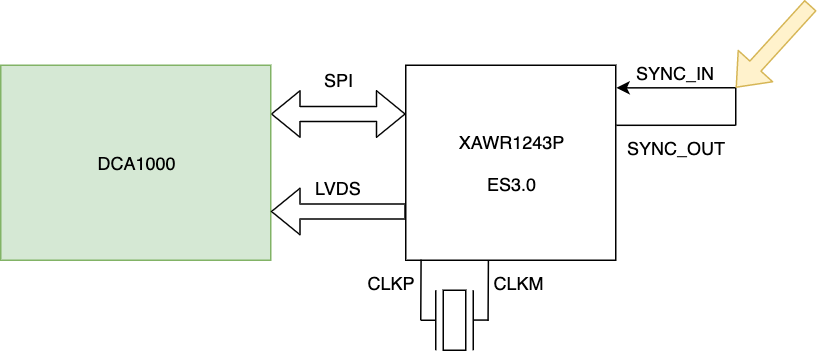
The XAWR1243P is configured as MULTICHIP_MASTER and set to software trigger. The chip is set to internal LO (INTLO_MASTER_EN). 

I configure the chip to transmit a single (1) frame with a period of 40 ms. I trigger the frame. I do not get any LVDS data out. Instead, I see this on the SYNC_OUT line (oscilloscope attached where the yellow arrow is shown above): 

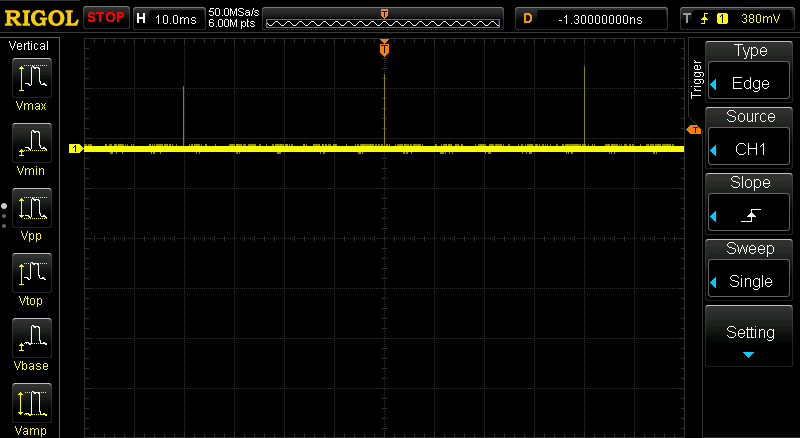
This is a continuous train of pulses on the SYNC_OUT line with a period of 40 ms. This runs forever. 

Any idea what's going on? 

In case it's helpful this is the trace.txt file of the SPI communications with the chip: 6013.trace.txt

Thanks very much for the help. 

  • Hello,

    I assume you are using mmwave to configure the 2243 device. If that is the case can you share the complete output log from the mmwave studio window from the start to the end of the configuration?

    Also how are you verifying that no LVDS output is available? Have you probed the LVDs lines to check them?

    Regards,
    vivek

  • Vivek,

    Thanks very much for the reply. 

    1. We are using the XAWR1243P (not the 2243). I don’t know if this makes a difference or not. 
    2. We are using the mmWavelink DFP to control the chip, connected via USB to the DCA1000. So no mmWave Studio.
    3. Since we are not using mmWave Studio I don’t have the output log in that format, however I do have a decoded trace of the SPI communications. See here: https://www.notion.so/kmb/SPI-trace-log-for-Vivek-3-20-8bd13bb635fb469891947b1ebf02633e 
    4. I know there is no LVDS output because the DCA1000 times out. Thirty seconds after arming, the red LED LVDS_PATH_ERR comes on.
    5. I also probed several LVDS lines with the oscilloscope: CLK_P, CLK_M, and FRCLK_N. These all showed constant value (high or low) during the interval between two SYNC_OUT pulses.

    Thanks!

    IB

  • Hello IB,

    Unfortunately I am unable to access the file location you shared. Could you attach the file in the post?

    Also could you confirm if the Sync out level you are seeing is reaching the IO voltage level (which would be 3.3V I guess)?

    regards,

    vivek