This thread has been locked.

If you have a related question, please click the "Ask a related question" button in the top right corner. The newly created question will be automatically linked to this question.

DRV5055: DRV5055 Sensing range ,Trade off between range and sensitivity

Part Number: DRV5055
Other Parts Discussed in Thread: DRV5056, DRV5057

Dear,

We are planning to use DRV5055 Sensor ,i already used the DRV5053EAQDBZR (EA: +45 mV/mT) Sensor but wasnt able to get the sensing range.

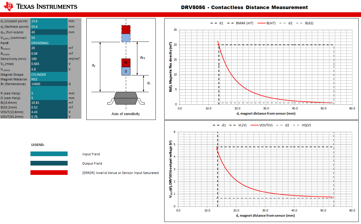
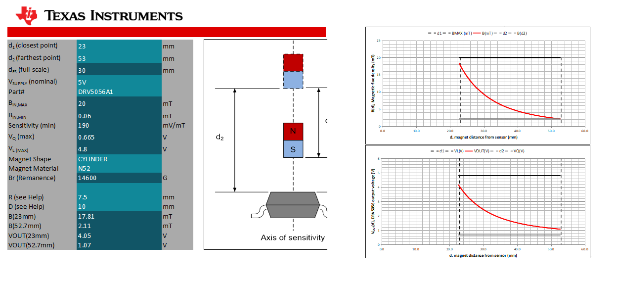
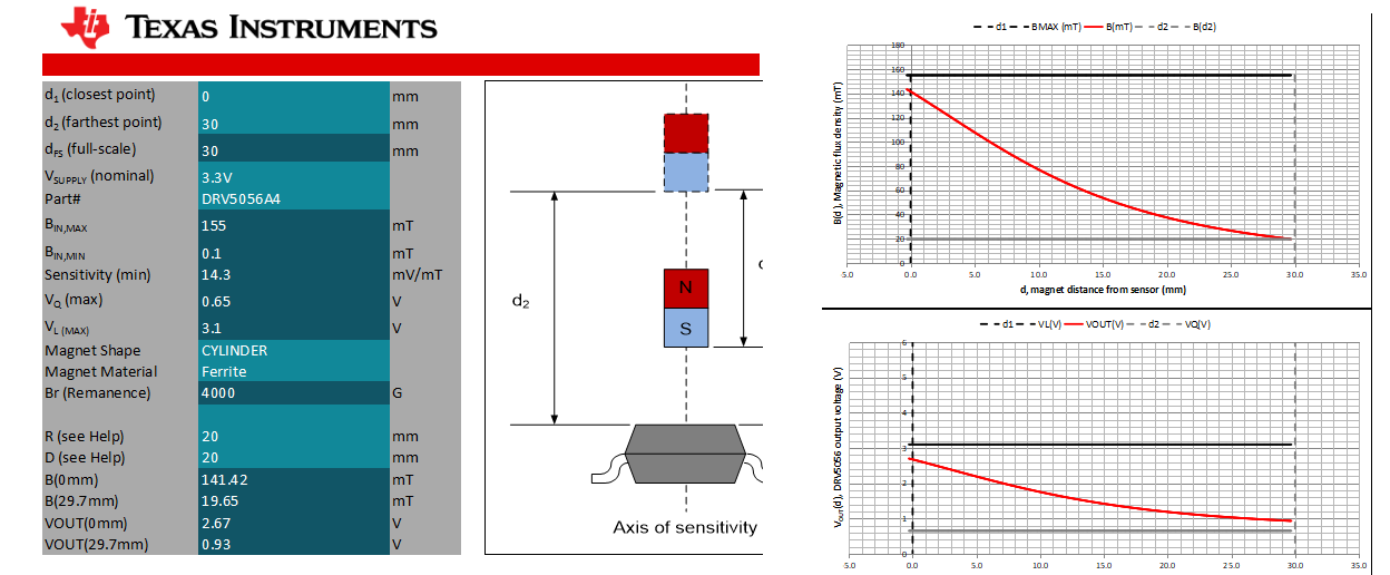
In our application we want a sensing range of 40 mm ,the magnet we are using are N52 Grade 10x5 mm (Dia x Thickness) magnet and accordingly to that i have calculated the magnetic field with the help of the Magnetic field calculator and getting a value of B=1.17 mT :

Below is my query which i would like to ask :

1)Will the DRV5055 Sensor sense from the 40 mm distance...?

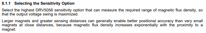
2)For better clarity which parameter specifies sensing range of the IC ?What is the relation with the gain..?

Also please suggest any other IC which would meet our requirement,Your help would be highly appreciated..!!


  • Hello Tirthal,

    Thank you for using the TI forum.  There are many aspects to think about here.  

    My fist note would be that if you are using a head-on approach (as in the magnetic calculator you used above), then you may want to use the DRV5056 instead of the DRV5055.  The DRV5056 is very similar, but is unipolar which will allow you to use the full scale range of the device if you only plan to use one pole of the magnet.

    Also, whether or not you can do this with just one sensor depends largely what kind of measurement resolution/accuracy you require. I recommend using the DRV5056 distance measurement tool to help you get an idea of what to expect.  The tool can be found here: https://www.ti.com/lit/zip/sbac231. This is an example of what it looks like with your specifications:

    I adjusted the start stop position to start farther away form the magnet (13.6mm) so that the sensor was not railed. I recommend trying different sensor versions and magnet shapes to get results that work for you. Note, the measurement resolution will be lower as the magnet gets farther away from the sensor.

    If you cannot find a setup that works for your accuracy requirements with just one sensor, you can use 2 or more sensors combined data to get better results across your whole movement path.  These options change significantly based on your design requirements/setup, so if you end needing more help with that, just let us know.

  • Dear,

    Ok got it.

    Below is my query :

    1)So in my case my range is more so  :Type ---> A1: 200 mV/mT, 20-mT range is suitable,means lesser the mT more is the range ,i am bit confused in this ,bcz somewhere it also specified that if you want range gain should be low.

    I want to understand this relation --> 200 mV/mT, 20-mT.and major difference between 

    A2: 100 mV/mT, 39-mT range 

    A3: 50 mV/mT, 79-mT range 

    A4: 25 mV/mT, 158-mT range

    A6: 100 mV/mT, 39-mT range

    After using the tool i understood that higher mV/mT and lower the mT more is the sensing range correct...??

    -->One more thing i am operating the system on the 3.3v.I am also attaching the 3.3 v and 5.0 v readings with d=15  mm and thickness 10 mm with N52 magnet.

    I think this results are good,correct?

    And the above with ferrite magnet,but do you suggest to use ferrite magnets considering long functioning of the device?

    And which DRV5057 is based on the PWM output so,which will give me more stability in the output with range ?Ratiometric output of the PWM output ?

  • Hello  Tirthal,

    There are a couple TI Precision Lab videos that I think you will be interested in.  Here they are:

    Understanding Key Specifications of Linear Hall Effect Position Sensors: https://training.ti.com/ti-precision-labs-magnetic-sensors-understanding-key-specifications-linear-hall-effect-position?context=1139747-1139746-1137749-1139634-1137744 

    Designing an Analog Proximity Sensor: https://training.ti.com/ti-precision-labs-magnetic-sensors-designing-analog-proximity-sensor?context=1139747-1139746-1137749-1139635-1137746 

    Here are my responses to your questions:

    • To help you better understand the sensitivity versions, let's look at the A1 device, which is A1: 200 mV/mT, 20-mT range
      • The 200mV/mT is the gain or sensitivity of the device.  This shows how much the device output will change given a specific magnetic field (at 5V).
      • the 20-mT is the magnetic sensing range of the device.  This means that the full scale output of the device corresponds from 0-20mT in measurement.  (Essentially the max output voltage = 20mT).
      • So, the A1 is considered a high sensitivity device, even though it has a low magnetic range. 
        • It is important to note that the sensing range is not the same as the measurement range/travel distance.
        • So, you are correct, in that a low gain/sensitivity has a high magnetic sensing range (ie, A4 has a low gain of 25mV/mT, but a high range of 158-mT), however this does not translate into a large travel distance, because magnetic filed drops off so quickly with distance.  
          • Because of this, you are correct in that you can usually get a higher travel distance with a higher gain and low range.
      • The datasheet says this about selecting a good device for your system:

    • Correct, your results look good, and it looks like you are using the tool correctly.  
    • In regards to Ferrite vs Neodymium, it really can depend on your setup and mechanical requirements.  Note that with a ferrite magnet, you ended up using a much larger magnet. Also, if you expect large temperature changes, then the Neodymium will give you more consistent results across temperature because the DRV5056 drifts with temperature to compensate for neodymium magnets.
    • The DRV5057 is the same as the DRV5055, but with a PWM output.  Ratiometric is not a great word to describe the DRV5057, because it has a PWM output, not a voltage output.  However, similar to the ratiometric parts, the DRV5057 will utilize the full PWM output swing regardless of if the device is powered up at 5V or 3.3V.
  • Dear,

    Yes that helped a lot ,so now i understood correctly that more the voltage swing 200 mV/mT but at the same time bigger the magnet to increase the sensitivity.

    Sorry for a spelling update ,i meant that in which configuration output is more stable PWM or the ratiometric.I know both application area are different but just for knowledge.

    Thanks ...!!

  • Hello Tirthal,

    Both the DRV5055 and the DRV5057 have about the same stability (ie, nose/accuracy).  Both devices measurement accuracy can be improved by averaging samples, and the DRV5055's accuracy can also be improved by filtering noise from the output (but this lowers the sensing bandwidth).   However, if there is a long distance from the sensor to the MCU, then the DRV5057 would be best to use, as the measurement result is not affected if the voltage declines over the long transmission path.