This thread has been locked.

If you have a related question, please click the "Ask a related question" button in the top right corner. The newly created question will be automatically linked to this question.

IWR1443: Tx-Tx leakage

Part Number: IWR1443

Hi,


We have discovered Tx-Tx leakage on IWR1443.


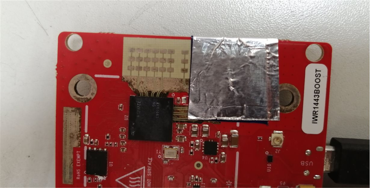
We measured IWR1443BOOST received signal voltage from reflector. Tx1 was open to air. Tx2 and Tx3 were covered with dielectric and aluminum foil.


Tx1 was active on first chirp. Rx signal was U.

Tx2 was active on second chirp. Rx signal was 10-15% of U.

Tx3 was active on third chirp. Rx signal was 10-15% of U.


But Rx signal corresponding Tx2 and Tx3 active should be zero.


The leakage was even more on custom board having longer Tx1 feed line and unconnected (cut off) Tx2 output.


What is the reason of leakage and how it can be reduced?


Regards,

Gennadii

  • Hi Gennadii,

    For Causes of the Leakage between Tx pairs we would have to see what is the nature of the leakage you see.

    Contributing factor could be device, board and field all combined.

    Based on that counter measure can be incorporated  in Design as well as post processing to avoid the leakage form causing detection errors.

    For example - if leakage shows detection in close range detection  then application can use the High Pass Filter  setting  in the device to filter out these near reflections.

    We will get back with more information. Please share more specifics of detection of needs and leakage seen to help you better.

    Thank you,

    Vaibhav

  • Hi Vaibhav,

    The leakage is a signal from the reflector.

    It's just a copy of signal U but having lower amplitude.

    Regards,

    Gennadii

  • Gennadii,

    Just to give some background here:

       As you would know Tx to Rx coupling at board level would be present, In Radar systems this is also termed as Tx to Rx leakage signal (This is undesired component). This would be appearing at lower IF frequency of the spectrum (frequency is dependent on slope and location of dominant coupling path i,.e. board level, Antenna, Radome etc. Isolation between Tx and Rx on board level is >30dB. Signal beyond this isolation would appear in the lower IF part of the spectrum. High pass filter would suppress it maximum up to 40dB depending upon where it would appears in the IF spectrum (Hence higher antenna isolation is always better to reduce this leakage signal). 

    Longer feed lines are susceptible for coupling (Grounded CPW transmission line works better compared to micro strip-line configuration) 

    In the above case: We have two mechanism

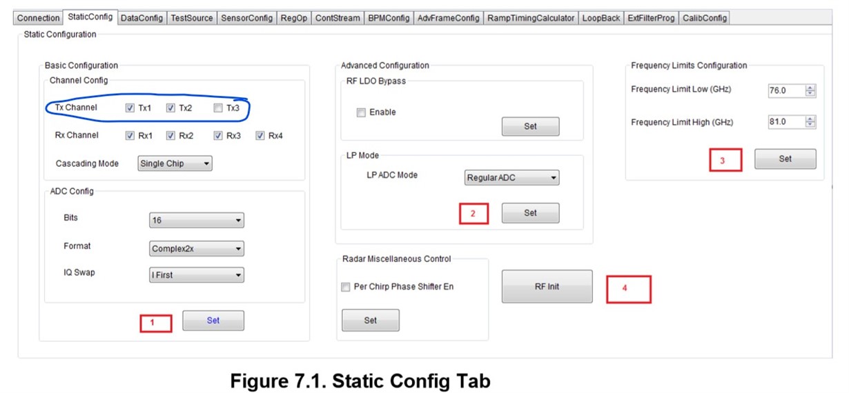
    1) Selecting right Tx chain through the profile configuration: In this configuration you could select right transmitter of your choice.

    However in this case other transmitter chains (Not selected) would be enabled but would not be chirping.If your design doesn't have other transmitter active at all then below 2nd option is better.

    2) In this option by selecting only desired Transmitter and receiver section completely shuts of other Tx and Rx pairs which are not selected.

    Hence you would not see any leakages, from other transmitter which are not in use in the system.


    These are screen shot from mmWave studio, however you could use the same APIs from the mmWave SDK as well to achieve same desired results. 

    Thanks and regards,

    CHETHAN KUMAR Y.B.

  • Gennadii,

          There are lot of level sensing customers using single Tx configuration in IWR1443 device.

    Typical absorbent material are not going to absorb 100% of incident energy, If the material type is not selected correctly, there would be reflection from the boundary and causing Tx, Rx coupling. 

    Did you try above step (2) ? Do you have measurement results? 

    Thanks and regards,

    CHETHAN KUMAR Y.B.

  • Hello Chethan,


    We have done step (2). Electrical tape and foil was used. We still have 12 dB leakages. We have seen Tx leakage for open antenna using our software but not RadarStudio.

    Regards,
    Gennadii

    Expirement_tx0_covered.zip

  • Hello, 

       Thanks for sharing the results,

    From the images shared 1) Tx open and Tx covered couldn't see the difference between the images. I guess this is just a typo. I couldn't see the step 2 configuration in the images that is attached.

    2) on the x-axis range bin where tx and Rx leakage seen seem to at higher distance than at where Antennas are located. Could you change the chirp, configuration and confirm this? It may be possible leakage would be coming from elsewhere.  

    3) Typically to suppress Tx-Rx leakage at board level / Ramdome level mmWave absorber materials are used. Foils are not recommended.

    https://www.cumingmicrowave.com/products/rubber-sheet-absorbers.html

    4) Are you saying leakage is seen in your software but not in the Radar studio, Could you please share the results between two.

    Typically in the design, higher Antenna isolation helps between Tx to Rx, Apart from that HPFs are used to attenuated the Tx / Rx leakage, Is there HPF corner frequencies are the same for both? 

    Thanks and regards,

    CHETHAN KUMAR Y.B.