This thread has been locked.

If you have a related question, please click the "Ask a related question" button in the top right corner. The newly created question will be automatically linked to this question.

TDC1000: TDC1000-TDC7200EVM only constant values

Part Number: TDC1000
Other Parts Discussed in Thread: TUSS4470, TDC1011, PGA460, BOOSTXL-TUSS4470

Hallo,

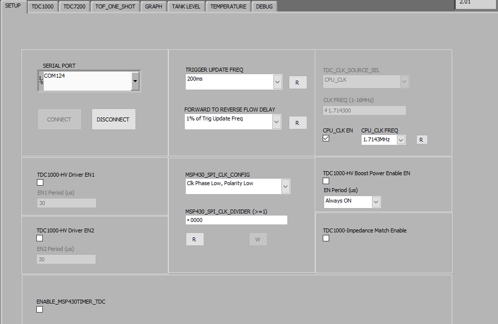
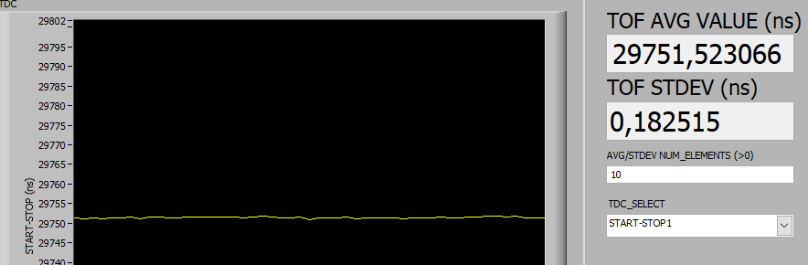
I bought the TDC1000-TDC7200EVM  a while ago. Now I finaly got time to try it out. I followed every step in the "TDC1000-TDC7200EVM User’s Guide ". I got the GUI running, but after the firmware update I got no signals from the device. I maesured and there was only a start Signal. After than resetting the TDC1000 via the GUI debug tab I finaly got Signals, but they were constant. I tried mouting the transducer on a sutible container an filling it with water, but i still got the same values. That made no sense. I tried playing with the settings, but I still dit not get anny usefull data. Reinstaling everything changed nothing.

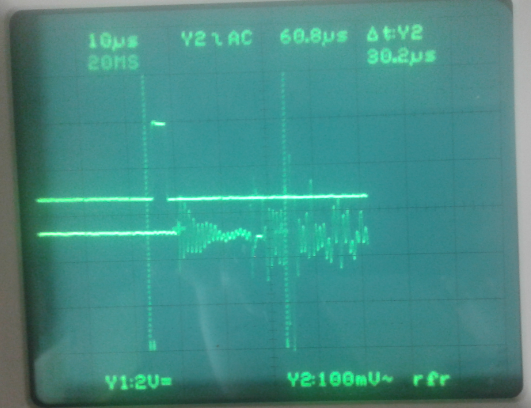
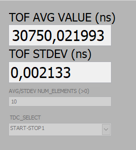
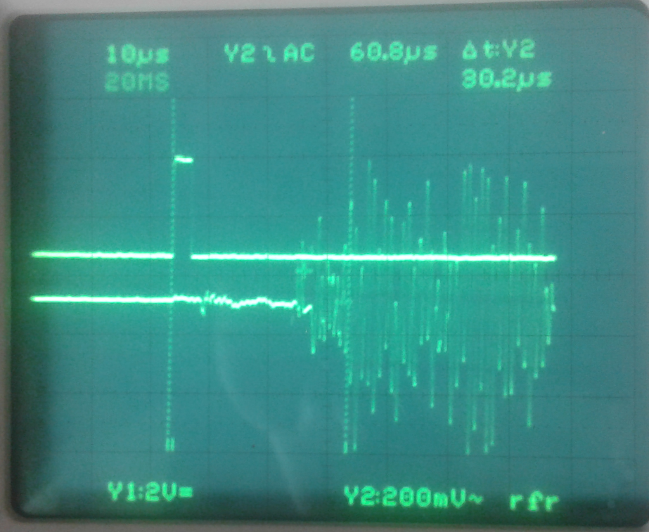
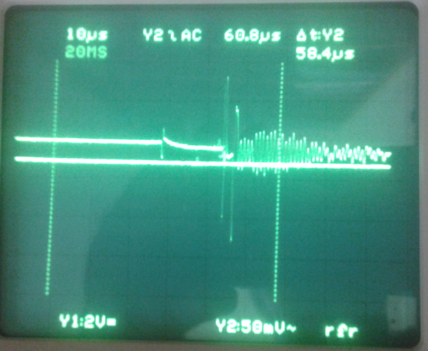
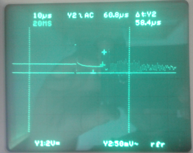
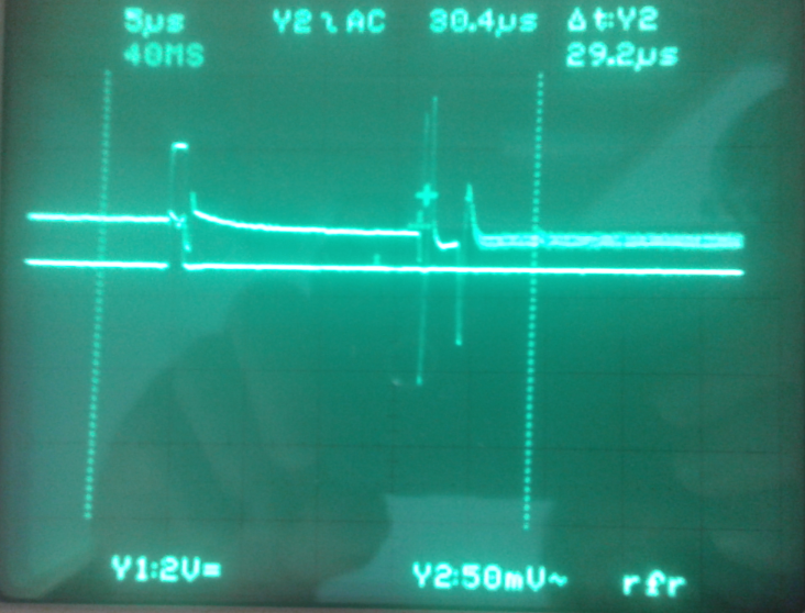
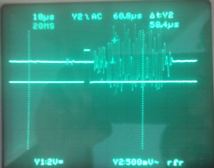
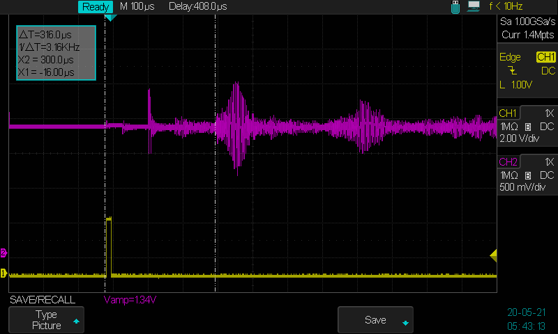
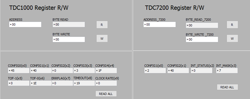
Here are the Registersettings and the result  I get.


I realy hope you can help me out.

Tobias

  • Tobias,

    Have you monitored the COMP_IN signal on an oscilloscope at time 30us from the START pulse? Usually a repeated value such as ~30us when using a 1MHz transducer is due to the threshold detecting the ring-decay of the transducer after burst. This ring-decay is reported as a false positive, and since it does not fluctuate, the readout value seems constant. This can be resolved in several ways:

    • Enable and increase the BLANKING and TIMING_REG value to delay echo detection to start after +30us. Depending on the minimum time of flight value you want to detect, you could set the blanking time to end just before.
    • Increase the threshold (ECHO_QUAL_THLD in CONFIG3) to be positioned above the amplitude of the ring-decay. This will prevent the ring-decay from intersecting and trigger a threshold detect.
    • On the Graph tab, instead of monitoring TDC_SELECT START-STOP1, monitor START-STOP2. The second stop pulse should be the real echo assuming the first echo is always the ring-decay created false positive. Note: you will need to enable multi-echo mode in RECEIVE MODE (CONFIG4), and set the NUM_RX to 2 STOP (CONFIG1).

  • Hallo Mr. Whitehead,

    thank you for the fast replay. I tried all your sugestions. I am currently working at home and I olny have one oscilloscobe probe at home. I got a Signal from the COMP-IN testpoints but without a second probe I can't tell the time after the start pulse. Never the less I tried out your solutions. Sadly nothing workt. Enableling Blanking sinply added the timeintervall i specified in the TIMING_REG to the values. So if I added 30us I would get values around 60us. Increasing the ECHO_QUAL_THLD value changed nothing. At -1500mV I no loner got any signal. All the other Values were more of the same.  Using the second stop pulse got me negativ Values (is that even possble with these chips, see immage).  Enabeling blanking had no influence on this behaviour.

    I also got myself yesturday some cheep transducer from amazon (supposed to bee a ultrsonic humidifiyer). I pluged them in, and got exactly the same problems. So I think there is a problem with the Bord, not with the transducer.

    Also isn't the ringdecay the reason way i was supposed to cover the transducer in Hotglue after gluing it to container?

    Is there anything else I can try?

  • Tobias,

    Without the ability to properly monitor the COMP_IN signal by using the START pulse as a repeatable trigger point, this will be a challenge to debug because you need to be able to visually inspect what the echo amplitude is to properly set the gain and threshold settings.

    Verifying a few items:

    1) Are you using a 1MHz transducer? The EVM-GUI is configured for 1MHz operation by default. Any other frequency may require hardware modification.

    2) How did you mount the transducer to the bottom of the container? Did you use the procedure described in the "How to Select and Mount Transducers in Ultrasonic Sensing for Level Sensing" app report ( https://www.ti.com/lit/pdf/snaa266 )? Improper mounting can result in no or poor measurement quality.

    3) What type of container are you using (thickness and material)? We have had success with plastic containers, but have not explored steel containers.

    A transducer will always resonate after burst, which is why a ring-decay will always be present regardless if you mount the transducer or not. The amplitude and duration of the ring-decay can be impacted (made weaker+short or longer) by the physical mounting, but not completely eliminated.

    If you want to ensure it is not an EVM failure, try making an open air time of flight measurement using a lower frequency transducer (i.e. 40-400kHz range) not mounted to the container.

  • Hallo Mr. Whitehead,

    thank you for your answer. Yes I have read the document on  how to mount the transducers. My Tank was made out of PP 1,5mm. I followed all the stepps mentioned. I used an Ethel-2-cyanacrylate glue whitch worked great.
    the sensor I used first was a SMD15T21R111WL wich was part of the dev-bord I baught. I also tries several HL0020-004 piezoelements from Audiowell whos resonance frequency was supposed to be 1 MHz+-1%.

    I also had an A-14P20  ultrsonic Sensor and tried to use it. The datasheet said that this one should have a resonance frequency of 40 kHz. I tried the whole frequency range by using TX-FREQ-DIV But I got nothing even when using the PGA from 3 - 18 dB. At 21 dB i wiredly enaugh got nearly the same signal  at TX-FREQ-DIV=4 as with the 1MHz transducers still konstant. That does not make any sense..
    Do I neet to conect the A-14P20 to different terminals than TX1/RX2(J5, pin 8) and GND(J5, pin 7), because of filtering issues? There was nothing about that in the Userguide.

    I will try another transducer from an HC-SR04 module wich i have used before in a hoby projekt. This one also has a 40 kHz resonance frequency. I know that this one works but I don't have high hopes.

    I still think there is something wrong with the Board

    Any other Ideas?

  • Hi Tobias,

    Regarding the debug using the 40kHz transducer, consider the following:

    • You must use an external clock source. The on-board clock source is referenced to 8MHz. In order to get from 8MHz to 40kHz, you would need to use a clock divider (TX_FREQ_DIV) of 200, which is not available on the TDC1000. Use an external clock source of 5.12MHz and a divider of 128 to achieve 40kHz for example.
    • Update the values of the external receiver network to enable a 40kHz to pass. The BPF network created by the default external components on the EVM allows for a 100kHz to 4MHz signal to pass. 40kHz will be heavily attenuated. To help you calculate appropriate external values for 40kHz operation, use the TDC1000 TINA-TI Reference Design.
    • The driver voltage requirement for many low frequency transducers can be >5V. An open-top transducer such as that from the HC-SR04 should work with a driver voltage of 3.3-5V.

    If you have your transducer connected to TX1/RX2, be sure to set the TDC1000 mode to MODE 0. you are correct: the positive terminal of the transducer should be connected to this net, while the negative terminal of the transducer should be grounded.

    Once you have access to a two channel oscilloscope to trigger from START and capture COMP_IN, we can continue the debug.

  • Hallo Akeem,

    I finaly got a second probe. I only have an old analog oszilicope but it still does the job. In the picture you see the signal, that I got from the mouted transducer. You can clearly see the ring attenuation, or what I percive to be the attenuation, in the first 10 us. But that is not the signal the bord ist trigerring on. The signal it self is very week an I tried to put the marker shortly before the trigeringpoints so that you can see the peak. With this I get about the same time measurement as in the TDC1000_7200_EVm-Software.  If I put water in the Container nothing changes not even a single diget. I played with the Gain-settings but that changed only the amplitude of the Signal. Still there was no difference with ore without water, or concentrates NaCl solution.

    When i Put the bare chinese Transducer from Audiowell in I got nearly the same signal with a higher amplitude. The TOF-Value was nearly the same. Here is a picture of the signal with the same Settings a before:

    there is no real ringdecay visible here and a far as I know, this transducer should not even work, because it is for mistmaking and requires much larger voltage. I got it for a nother project and just pluggt it in.

    From the same project I got an 1,7 Mhz transducer. And that one gives me nearly the same Signal wich should not bepossible,  because we dont use the right resonance frequency.

    I also tried using Blanking. But the signal just looked the same but was moved by the specified time and was more atenuated the bigger  that amount of time was.

    So I am still puzzeld by this behaviour, but maybe you can make sens of this.

    Stay safe and healthy

    Tobias

  • Tobias,

    Based on your screen capture, there appears to be a larger than usual amount of noise present at the input of the AFE. This is either coming from the transducer itself, or one of the internal rails of the receiver path is unstable.

    First, let's debug whether it is the transducer by performing a listen only measurement. You have two means of accomplishing this:

    • Using your existing connection, set the number of pulses to 0, and start a measurement. By setting pulses to 0, the transducer itself will not be forced to resonate, and will only respond to external noise (if present).
    • If you are unable to set the number of pulses to 0, but still minimize to 1 pulse, connect your transducer to Channel 2, and change your ToF mode setting such that Channel 1 (TX1/RX2) transmits, and Channel 2 (TX2/RX1) receives. This will isolate the driver from the receiver path.
      • Another experiment to perform in this configuration is to connect Channel 2 to ground. When you capture the ToF at COMP_IN, the signal should be at the input referred noise (which should be very low). If the large noise signal appears even when the receiver input is grounded, then there is either an external component or device failure.

    To see the burst and ring-decay waveforms on the scope, you need to enable FORCE_SHORT_TOF; otherwise, these signals will always appear masked/hidden as you've shown.

    It is important while performing this benchmark testing that the transducers not be mounted to the tank, and instead they be positioned, pointed, and encased by an absorbent sponge like material. For transducer debug, minimizing the number of external and mechanical variables is important.

    Be sure that you are probing the buffered output version of COMP_IN, and not the COMP_IN pin directly. The oscilloscope probe at COMP_IN can distort and amplify noise of the waveform.

  • Hallo Mr Whitehead,

    thank you for your fast reply and being so patient with me. This is really not easy for me and I always think that there is some stupid little detail I am missing. But back to the matter at hand.

    It was quite the hustle to get the transducer off the container. It looks rather ugly now but it is not broken. I found an unused PE sponge, cut i open put the transducer in  it, and wrapped a towel around the contraption for good measure. I set the numer of pulses to 0 by sending a Hex 40 command to the CONFIG0 Register. At first I got no Signal at lest nothing that comes close to the signal I had before. Then I lowered the trigger and got the signal you see below (other V division!!). It is not much longer than you can see. Changing TRIGGER UPDATE FREQ did not influence the signal. 


    By the way this signal did not change, when I removed the transducer from the sponge.

    With your second Method I was not sure how to achieve that. The datasheet doesn't even mention that possibility as far as I understand it. But I tried according to the description on page 20 and 21 in the datasheet. I set TOF_MEAS_MODE to 1, shorted the TX1 to ground and put the Transducer in RX1. Using this method I got the same Signal as above, but now it triggered together with the start signal. The signal did not change regardless with or without sponge. When I tried the same with TOF_MEAS_MODE =0  i.e. grounding TX1 and putting the Transducer in RX2 I got the same unchanged signal as I described in the last post. Are those shorted together?


    Weirdly enough, when I removed all cables in TOF_MEAS_MODE = 1 configuration, I still got two small peaks after the start signal on the COMP_In line. See Below. Is that normal? I also did this with TOF_MEAS_MODE = 0 and no transducer attached and sure enough these two peaks are still there but more attenuated.


    Now I tried to get the burst and ring decay as you described. I reset everything, put the transducer in TX1/RX2 and enabled FORCE_SHORT_TOF. Now I got the following signal. That is not what I expected. I was expecting four more or less identical peaks and then a damped sine-wave. But of course I don't have enough experience to judge that.


    I retried all the above mentioned tests with the Audiowell-transducers I mentioned before and got more or less the same results.

    I hope you can make something of this.

    Stay safe and healthy

    Tobias

  • Hi Tobias,

    I will capture a 40kHz transducer air-coupled time-of-flight example using the TDC1000-TDC7200EVM to help provide you with a working reference to include settings and oscilloscope results. This will help determine if your EVM hardware is faulty or not. I will have this information available the week of May 18th.

  • Hi Tobias,

    I've captured an alternative working example at 220kHz. Here are the test conditions:

    • EVM Hardware: TDC1000-TDC7200EVM (Red Board)
    • Transducer: Massa E-188/220 (220kHz) with 3.3kOhm damping resistor in parallel to the transducer.
    • Target: 24cm water level from top of water surface; transducer face is submerged in water. Assuming speed of sound is 1500m/s in water, the round trip time of flight will be 320us.

    Here is a photo of the physical setup:

    Here are the oscilloscope results:

    • CH1 (yellow) = START pin
    • CH2 (red) = COMP_IN (buffered output)

    Notice the delta between the cursors is about 316us from the START pulse to the beginning of the first echo at COMP_IN. This is our 24cm level sensed height.

    Attached is the GUI configuration file for the TDC devices and snapshots of the GUI setup:

    TDC1000_Config0                         4A
    TDC1000_Config1                         40
    TDC1000_Config2                         04
    TDC1000_Config3                         00
    TDC1000_Config4                         5F
    TDC1000_TOF-1                           E3
    TDC1000_TOF-0                           FF
    TDC1000_Error_Flags                     00
    TDC1000_Timeout                         00
    TDC1000_Clock_Rate                      00
    TDC1000_Conts_Trigger                   00
    TDC7200_Config1                         00
    TDC7200_Config2                         00
    TDC7200_Interrupt_Status                00
    TDC7200_Interrupt_Mask                  00
    TDC7200_Coarse_Cntr_Ov_H                FF
    TDC7200_Coarse_Cntr_Ov_L                FF
    TDC7200_Clock_Cntr_Ov_H                 FF
    TDC7200_Clock_Cntr_Ov_L                 FF
    TDC7200_Clock_Cntr_Stop_Mask_H          00
    TDC7200_Clock_Cntr_Stop_Mask_L          00
    TRIGGER_UPDATE_FREQ                     0001
    TDC_AVG/STDEV_NUM_ELEMS                 000A
    SAVE_GRAPH_DATA_TO_FILE                 00
    FLOW_MODE_SELECT                        00
    Y-SCALE_CENTER                          0032
    X-SCALE_RANGE                           0032
    MEASURE_RTD1                            00
    SAVE_RESULT_REGR_TO_FILE                00
    GRAPH_MULTI_STOPS                       00
    TDC_SELECT                              00
    TEMP_RTD_SELECT                         00
    TEMP_RTD_MODE                           01
    TEMP_AVG/STDEV_NUM_ELEMS                000A
    SAVE_TEMP_DATA                          00
    GRAPH_YMAX_DATA                         00000000004C4B40
    GRAPH_YMIN_DATA                         0000000000030D40
    TDC1000-HV_DRV_EN1                      00
    TDC1000-HV_DRV_EN2                      00
    HV_DRV_EN1_Period                       001E
    HV_DRV_EN2_Period                       001E
    ENABLE_POWER_CYCLE                      00
    CLK_FREQ_(1-16MHz)                      1.714300
    CLK_SOURCE_SEL                          03
    CPU_CLK_FREQ                            0A
    CPU_CLK_EN                              01
    TDC1000-HV_BST_PWR_EN                   00
    HV_BST_PWR_EN_Period                    0000
    FWD2REV_FLOW_DELAY                      0000
    TDC1000-IMPE_MATCH_EN                   00
    ENABLE_UART_STREAM                      00
    ENABLE_MSP430TIMER_TDC                  00

    Notice the CPU_CLOCK is set at 1.7143MHz. So when we apply a clock divider of 8, the resulting driver pulse is 214kHz, which is very close to the 220kHz requirement of the transducer.

    I hope this serves as a good working benchmark to test your setup. You may need to get a sample of the same transducer for an exact comparison, but the point of this exercise is to show you the typical levels of the COMP_IN output, which should not be as noisy as you have shown in your previous oscilloscope captures.

  • Hallo Akeem,

    Thank you for all the work. I will try to get my hands on the transducer you mentioned. Sadly there is no european supplyer. I have contected Messa directly, but as you might know, this might take a while.

    In the mean time I will get my hands an two US0014 1mHz transducers from audiowell shortly. In the Document "How to Select and Mount Transducers in Ultrasonic Sensing for Level Sensing and Fluid ID " from TI they are discribed as working with the original setup.

    So I will try them out and get back to you either when I get my Hands on the Massa E-188/220 or if it works with the US0014

    Until then stay Safe

    Tobias

  • Hallo Akeem,

    Thank you for going through all the trouble. I do not have this kind of transducer an so far as I see i there is no sell for it in Europe. I tried to contact the manufacturer but so far nothing.

    I have a friend who borrowed me a 113 kHz transducer. I used the CPU Clock with 1,8462 MHz and a divider of 16 to get to 115 kHz. As a reward I got a small but clearly audible chirping Sound from the transducer.  How that can be at 113 kHz  is beyond me but ist shows, that at least the excitation of the transducer works. I still do not get a usefull distance measurements in Air or water but that is not a surprise, as this is not the right kind of transducer to act as a receiver.

    I also tried to use the CPU clock with the 1MHz transducer with the CPU clock at 2 MHz and a divider of 2. That did not work either but now instead of constant 30 us TOF I got 100 - 110us. Well, I think I need to get a MassaE-188/220 for good comparison. I will try to get on

    Stey save

    Tobias

  • Hi Tobias,

    While you wait on the Massa E-188/220 transducer, are you able to consider using a different ultrasonic IC? The TDC1000 is typically recommended for applications that require BOTH level sensing and concentration measurements. However, if you only need level sensing, we have a few single channel device alternative available. Of course, there is the TDC1011 (one channel variant of the TDC1000), but I typically recommend either the TUSS4470 if you need to use transducer up to a 1MHz frequency, or the PGA460 for transducers operating up to 480kHz in frequency. Both the TUSS4470 and PGA460 are far more integrated and better performing than the older TDC1000.

    I see you're a university student, so I understand if you don't have a choice, or if you need to use a transducer above 1MHz up to 4MHz - then the TDC1000 is your only TI option. It's because of issues like what you are experiencing why we tend to recommend the TDC1000 as a last resort. If you'd like to see more information and comparison of the various TI ultrasonic time of flight devices, see the E2E FAQ here: https://e2e.ti.com/support/sensors/f/1023/t/748143

  • In reply to Akeem Whitehead:

    Hallo Akeem,

    I have got two Audiowell transducers US0014-001 which should work according to the TI-Documentation. But they do not. I can't get the Transducer you suggested. There is simply no supplier in Europe or a least none who wants to answer my request.

    To answer your question. I only need the concentration measurements no level sensing. I am trying to develop another method for the measurement of particle size distributions for mineral soil samples. Right now believe it or not this is done by hydrometer. (To get an Idea https://www.youtube.com/watch?v=78sKJKsaUvY) It takes forever and is very labor intensive. There are alternatives with dynamic light scattering but those are rather expansive. I know that there are ultrasonic density sensing solutions out there that are sufficiently precise but they are used in chemical or water plants and are not useful in this context and also cost about 10000€ (for example: https://www.sensotech.com/en/products/sensors/immersion-sensor-40-14-lab). My Idea was to build a specific and automated system with very precise density measurements in the sedimentation cylibder itself. As I see it I would be stuck with the TDC1000. I am not a student. I am a labassistant who does the od electrical stuff on the side that comes up all the time in an university lab.
    We have contact with a company that is interested in the Idea but they wanted at least a working example before committing more resources. That is why I bought the dev-Board. It should in principle be good enough to show if the principle is sound. But as you know I am not there yet.

    Well I tried everything I could think of. Either the Board is not working, or there is a mistake I am making. Either way I am not getting anywhere. Maybe you could tell me if the Idea in principle is sound or if this was bound to fail anyway.

    Thank you again for all the work you put into this.

    Stey Safe

    Tobias

  • Hi Tobias,

    In principle, I suspect ultrasound can still be used in this type of density/concentration measurement application. The TDC1000, PGA460, and TUSS4470 can all be used for these measurements; the limitation of which device is dependent on the transducer frequency.

    Since you are in need of a high precision measurement, I recommend trying the TUSS4470 as an alternative. This device offers both an echo interrupt pulse (like the TDC1000's START/STOP pulses) and an analog output waveform for you to perform either a timer based capture to compute the time of flight or ADC based post processing. The BOOSTXL-TUSS4470 EVM is available to aid in this evaluation. I will send you a private E2E message with additional details.