This thread has been locked.

If you have a related question, please click the "Ask a related question" button in the top right corner. The newly created question will be automatically linked to this question.

PGA305EVM-034: GUI calibration failed

Part Number: PGA305EVM-034

Hello,

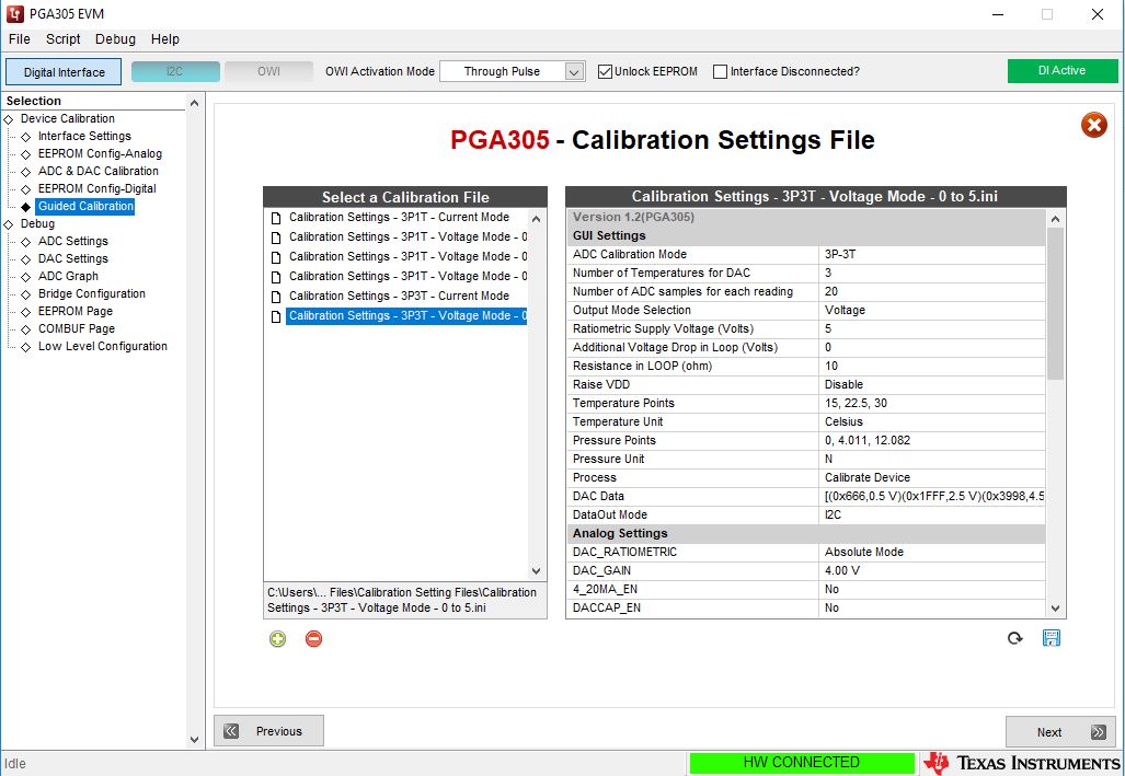
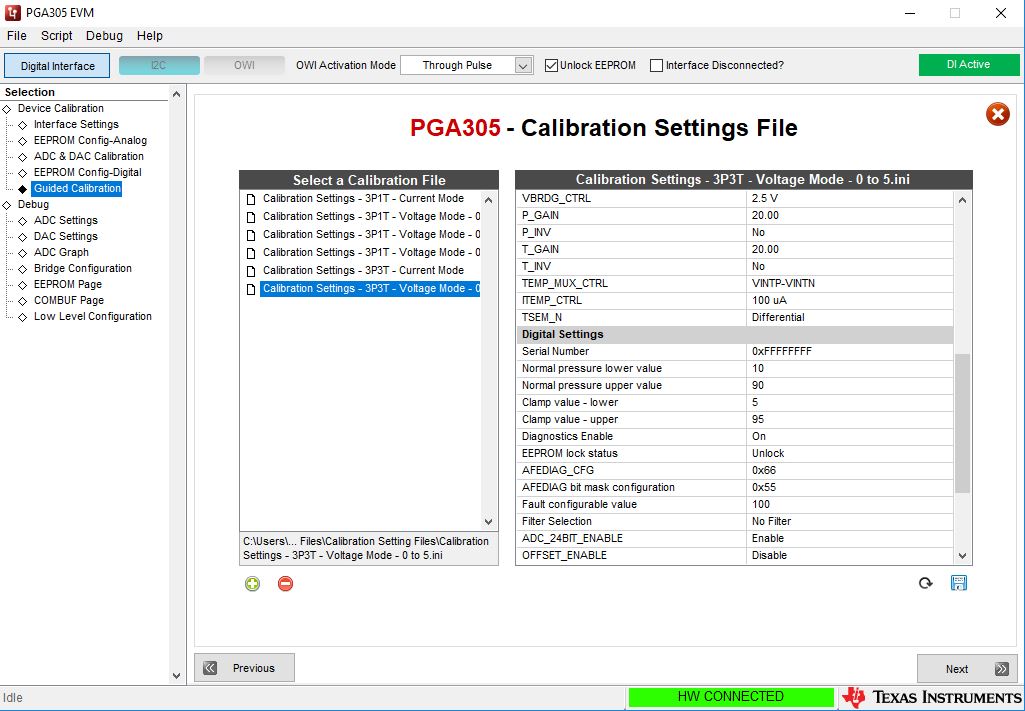
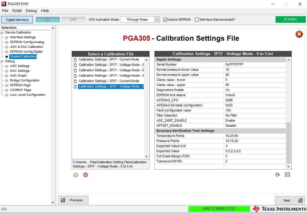
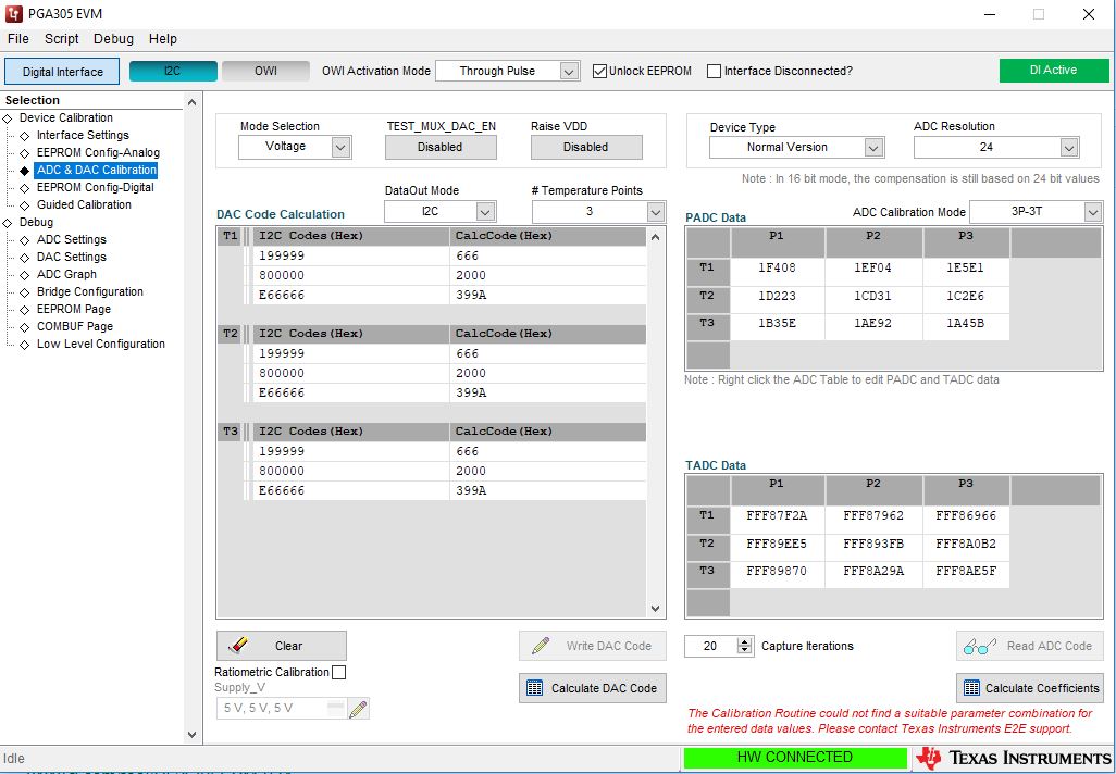
I tried to do a guided 3P3T calibration with the GUI and it failed. I am attaching the settings and ADC results. I tried to do the calibration without the verification.

I have a Wheatstone bridge where one resistor is the active strain gauge (350 ohm) and the other 3 are fixed resistors (also 350 ohm). The strain gauge is glued on to a metal (aluminium) rod and this is placed inside a thermal chamber. The resistors are also inside the thermal chamber and the EVM board is outside. The EVM power supply is 24 V.

The temperature sensor is glued on to the metal rod in close proximity to the strain gauge. The sensor is PT100.

Looking at the ADC graph tab I can see the temperature and force changing so the measurements are working ok. I am actually trying to measure force not pressure but I don't think this is the problem as the principle is the same. When changing the temperature I waited for the temperature to stabilise (about 1 hour) and when changing the load I also waited for a few minutes. The aluminium rod has a high enough mass so that the temperature doesn't change rapidly when I opened the thermal chamber. I used another PT100 to monitor the temperature of the metal rod independently of the PT100 used for calibration.

When I was doing the calibration I didn't know what values should I use for the I2C codes so I just left them as they were (you can see that in the picture).

What was I doing wrong and how can I successfully calibrate the device?

Kind regards,

Jure

  • I forgot to mention that I limited the power supply current as recommended with a 220 ohm resistor. That should provide about 110 mA which should be fine.

  • Hi Jure,

    Do you intend to use the analog output of the PGA305, or are you only looking for the compensated I2C output? If you want to get a DC voltage output from the device, you will need to set the DataOut mode to DAC on the ADC & DAC calibration page.From there you can adjust the initial DAC setting values so that they are near your desired voltage output for each pressure point. 

    Even if you want to use the I2C output, at the moment I recommend just using the Voltage DataOut mode for the calibration. The mapping to the DAC output only happens to the data the goes to the DAC, and the compensated I2C data is output before that mapping occurs. You can leave the DAC values and desired output values the same as those used in the configuration file you've shown. You will need to complete the calibration process this way, but if you don't want to measure the actual DAC output for each step, you can click "Write DAC Code" and then enter the same value that you have in the Desired_V column for each point. Once that is done, when you click "Calculate DAC Codes" the CalcCode Column should have the same values as the DAC Codes column.

    Additionally, how have you set up your external temperature sensor schematically? The values you're getting between temperatures doesn't seem to be changing very much between T2 and T3. If you are using differential mode for the temperature sensor you will need to connect the VINTN pin to ground to get a good measurement.

  • I only need the compensated I2C output. My final application will not use the DAC output so I wanted to do the same process as I plan to do in the final application.

    I connected the temperature sensor directly to INT+ and INT- pins (TP29 and TP27). In the calibration settings I have set it to differential. The temperature difference was 15°C (temperature points are 15°C, 22.5°C and 30°C). I also removed the J1-3 jumpers and left J22 and J23 installed.

    How do you recommend that I connect and set up the temperature sensor? I have 2 wires coming from the PT100. Currently the wires are quite long (about 50 cm) so there is some error, but the final application will have the wire length at 5 cm max. I also plan to use PT1000 but I don't currently have any available.

    I can try to use the DAC output and calibrate it that way but I would try to avoid that to make it the same as I have planned for the final application. I am still designing the PCB so I will be able to put additional test points in case I will need to use the DAC voltage out calibration option.

    In the calibration settings there is a "Resistance in LOOP (ohm)" option that is set to 10 by default. What does this value mean and do I also need to change it?

  • Hi Jure,

    The main concern for setting up the temperature sensor is simply to connect VINTN to ground. Your application should be fine otherwise.

    If you use the DAC output mode for calibration, but you don't actually intend to use the DAC, you won't have to measure anything. Simply enter in the same value that you have in the "Desired" column after writing each value. This just passes everything through without remapping the DAC output at all. This is all irrelevant to the i2C output, but it at the moment it appears like the best way to get the calibration to function as expected.

    If you were using the PGA305 in a 4-20mA current loop output mode with OWI communication you would set this value to reflect any additional resistance you have in the loop, so that the EVM circuitry could compensate for it and ensure that the OWI levels were correct. Since you're not using the DAC output or OWI, you can ignore this.

    Regards,