This thread has been locked.

If you have a related question, please click the "Ask a related question" button in the top right corner. The newly created question will be automatically linked to this question.

IWR6843ISK-ODS: IWR6843ISK-ODS looking for usabele IO pin

Part Number: IWR6843ISK-ODS
Other Parts Discussed in Thread: MMWAVEICBOOST,

Hi

I want to use the IWR6843ISK-ODS + MMWAVEICBOOST for a Fall Detection application with the option of not using a GUI.

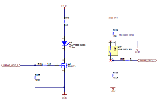
Are there any usable GPIO pins on the MMWAVEICBOOST  i can use to turn on a LED ?

And if there are pins how do you reacht them in the code on CCS?

Thank you in advance for any help and clarifications 

From Max

  • Hi,

    There are GPIOs on the MMWAVEICBOOST as shown below, GPIO2 is connected to the LED.  Please review the SDK Out of the box demo for the implementation.


    Charles O

  • Hi Charles

    I found the GPIO_2 LED on the MMWAVEICBOOST and in the source code. (main mss)

    But that LED is used to indicate that the sensor is running and  i'm not sure how to use it in a algorithm.

    Can you use it outside of the main file or should your algorithm be in the main file?

    Or is it possible to use one of the 40 pins (J5 & J6) on the back?

    Regards,

    Max

  • Max,

    You can route the GPIO to the  40 pin connector on the back by setting S1.10 OFF,  this does not disconnect it from the LED or switch on the board, if you really need to remove R128 & R121.

    There is also a simpler example in the SDK for the GPIO that may be easier to review for learning purposes

    mmwave_sdk_xx_xx_xx_xx\packages\ti\drivers\gpio

    Charles O