


Hello,
I am trying to understand the azimuth-elevation heatmap calculation within the point cloud demo for the ODS sensor. I found good documentation that explains most of the steps for the AOP board which has a similar antenna pattern with the ODS antenna. So, I will use the AOP example for simplicity.
One of the steps is still not very clear to me, more precisely, I'm trying to figure out how is FFT operator applied towards the obtained mapped antenna symbols after the step of Doppler calculation.
Here is the screenshot from the AOP document:
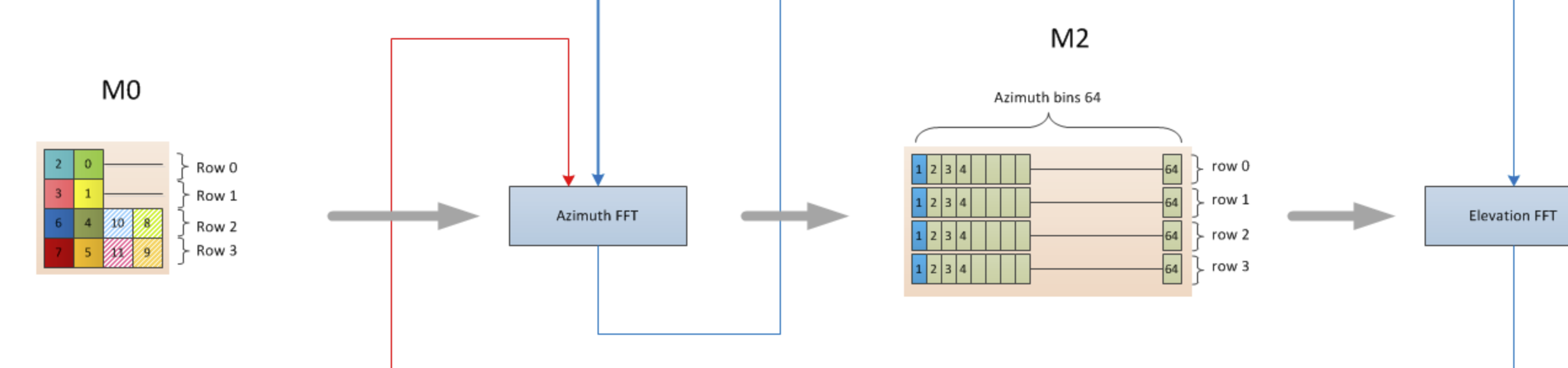
More precisely, I'm trying to understand how are the azimuth bins (M2) are formed from the mapped antenna symbols (M0).
Would it be correct to assume that each row in azimuth M2 memory is formed as a result of an operator Azimuth_row_i = FFT(M0_row_i, 64) ? I assume the 2D matrix that is kept in M0 memory has each symbol as a complex number (for example green "0", yellow "1" - each represents a complex value) - is that correct?
If the above assumptions are correct, then it means we are taking FFT of a vector of max length of 2 for rows 0,1 and 4 for rows 2, 3 and then pad it with trailing zeros to get the result length of 64 similar to Matlab's function FFT(row, 64) where length(row) is 2 or 4.
Wouldn't the input of length 2 and 4 be too short for the FFT() operation in order to get a meaningful result? Would be great to get clarifications on this part of calculation.
