This thread has been locked.

If you have a related question, please click the "Ask a related question" button in the top right corner. The newly created question will be automatically linked to this question.

LMP91200: Using several LMP91200 in one design

Part Number: LMP91200
Other Parts Discussed in Thread: INA121

Hello!

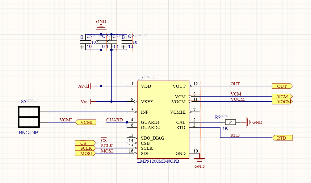
I am developing 4-channel ion meter, and plan using LMP91200 for it. The question is - how to connect 4 parts to have one common VCM output for single reference electrode and 4 ion electrodes? Is it ok to connect all VCM outputs together, or it should be dasy chained somehow?

  • Oleg,

      Help me to understand how you want to use 4 sensors with one LMP91200. How do you intend to get 4 sensors connected to one VCM and one INP?

  • No, I need to use 4 LMP91200 to monitor 4 sensors, but one reference electrode.

  • Oleg,

      That makes more sense.

      I am not sure it will be possible to combine VCM pins from 4 IC's. The issue is that it is the delta between VCM and INP that provides the output.  This signal is measured in uV and combining them could loose the resolution and accuracy needed for the final measurement.

    It would make more sense to use a common VREF in to each part. This would nearly be the same as combining VCM but will not incorrectly load the VCM buffer output.

  • Ok. The question is - if reference electrode is connected to VCM of first IC, and rest VCM's is left floating, will the measurement on all IC's be accurate? Consider VREF is common.

  • Oleg - 

    it would seem that this would lead to inaccurate measurements, as the voltage at the VCM pin does represent the internal zero, and the INP voltage is referenced to it. 

  • And so, what is the solution? Maybe VCMHI can be used as input for VCM buffer? Or maybe I can tie all VCM pins together?

    Again: the task is to use one reference electrode and 4 ion selective sensors.

  • Maybe I can use only the sensor amplifiers on secondary LMP91200's, without using VCM terminals, and connect VOCM of first LMP91200 to all 4 negative terminals of ADC's? In this solution VCM and VOCM of secondary LMP91200's are left floating and VCM is used only as internal reference, and as sensor amplifiers of all IC's configured as unity gain amplifiers, so it is directly reflects input potential, the error could occur only very close to power rails, which is acceptable, as usually the input potential is inside +-1000mV range?

  • Oleg - 

    do you have a part number of the sensor you are using that you can share? This is a unique method that you are proposing, therefore more information about it would be most helpful. Schematic or block diagram (concept is OK) would also be helpful, just so its really clear what you intend to do here.

  • This is custom ion-selective sensors made by our partner here in Russia. It is used generally for hydroponic liquids and soil analysis. Mainly, these sensors have same characteristics as pH sensors, except there are no internal reference electrodes used, but one common reference electrode. 

    It is easy to consider these sensors as usual pH sensors without embedded reference electrode. BTW, we also have pH sensors with same design - with separate reference electrode.

    Currently measuring channel design is:

    One more note: the design supports connecting 4 pH sensors with their internal reference channels, but reference electrodes for these channels are tied together. And we have the connect-sensing plug for common reference electrode, which is disconnecting outher (shielding) contact of BNC connector for each channel from VCM, as the common reference electorde also works well for pH sensor.

  • Currently existing design (but it's performance is rather not good because of too low input impendance of INA121) is:

  • One more point: our design also contains factory 2-point calibration procedure with precalibrated voltage source (2 points, one - terminals are shorted, second - 2048mV are aplyed to terminals), and so the constant offset error constant gain error in each measuring channel has no matter as it is compensated by software.

  • Oleg,

     This part is designed to correct the offset error, set a zero reference and correct for voltage error over temperature. That being said, the VCM buffer is capable of driving up to 8mA, which should be enough for four VCM nodes. you can't connect four VCM nodes together as they are push - pull (or sink - source) in the VCM output. The first VCM to output a few micro volts higher than the others will send the other VCM outputs into sink mode, when they sink the highest VCM output will source max current while the others will sink, this will begin an oscillation of shorts and opens. (Not good) 

    If you decide to use one VCM to power four sensors, the VCM output will have extra loading from each sensor causing a voltage drop of micro volts as each one is added. This will cause error in the measurements. As you said you go through cycles of calibration, so you may overcome this error. There is no guarantee the zero will be correct for all 4, and the voltage correction over temperature for the VCM may not be valid.

    You will need to apply the same VREF voltage to all circuits as the internal connections need to see this reference. Your differential measurement will be incorrect as well because you have to use the VOCM and VCM of only one IC for all four ADC differential inputs. Power and connect all pins of the IC as it was intended, except only connect the output VCM, VOCM and VCMHI of one IC to your application.

    To be honest, this chip was not designed for this application and TI will not be able to warranty or guarantee its use or specifications. However it's well worth the effort to try it and see what happens. 

    It's difficult to tell you what the results will be when your application is outside of the intended design application. I would be interested to hear what the outcome of this design is and how you overcome the design challenges.   


  • Ok, we will try to make draft design and will report its performance. 

    Thank you.