This thread has been locked.

If you have a related question, please click the "Ask a related question" button in the top right corner. The newly created question will be automatically linked to this question.

LDC1312-Q1: Recommended design When Sensor-Target Distance is over 5mm

Part Number: LDC1312-Q1
Other Parts Discussed in Thread: LDC1312

Hello

My Customer will Design the Inductive sensor using LDC1312.

The maximum size of the PCB is 7mm x 7mm.

Could you suggest design When Sensor-Target Distance is over 5mm?

It should be detected when the distance between the sensor and the target is 5mm or more.

LDC1312_Tools-ext49_Itops.xlsx

Best Regards

  • Hello, 

    Thanks for your interest in using the LDC parts. In regards to your application. Can you please help us understand what is the maximum distance the target is at compared to the coil ? Most LDC devices can sense upto 50% of the coil diameter. We recommend that the maximum target be with in < 10 cm. 

    If your target distance is 5 mm I recommend that your coil be designed such that its 2x the maximum distance which is 10 mm. 

    For more information please look at our FAQ section that provides you the guideline.  https://e2e.ti.com/support/sensors/f/1023/t/295036 

    Here is the link to get more information on how to use the lDC calculator to fit your application. https://e2e.ti.com/blogs_/b/analogwire/archive/2016/11/29/how-you-can-use-the-ldc-racetrack-inductor-designer-tool 

    Let me know if this helps! 

  • Hi Arjun

    Thanks for your support.

    How to detect Sensor-Target Distance is over 5mm when PCB size is 7mm?

    Please suggest possible solutions.

    Best Regards.

  • Hi Arjun

    Thanks for your support.

    How to detect Sensor-Target Distance is over 5mm when PCB size is 7mm?

    Please suggest possible solutions.

    Best Regards.

  • Hi Louis,

    Few more questions here Can you please help me understand if PCB size is 7mm is that the total solution size ? Can you please elaborate if the size is 7mm x 7mm. 

    Also, what is the shape of the target and what is the maximum distance the target is expected to be at ?

  • Hi Arjun

    I  answer the your question.

    Few more questions here Can you please help me understand if PCB size is 7mm is that the total solution size ? Can you please elaborate if the size is 7mm x 7mm. 

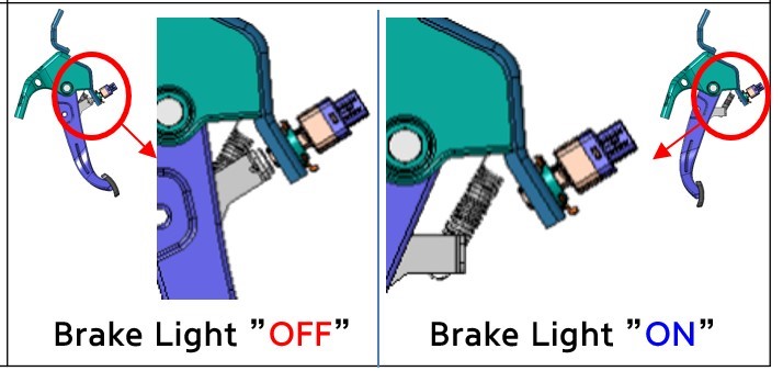
    Stop Lamp Switch  PCB Dimension is as below

    Sensor coil will be mounted on the 8.5mm width PCB.

    Also, what is the shape of the target and what is the maximum distance the target is expected to be at ?

    Distance requirent is More than 5mm between Stop Lamp Sennor and Pedal(Iron).

    In other word less than 5mm brake_lamp should not be turned on.

    So we need to know how to enlengthen the sensing disance.

    Best Regards.

  • Hi Arjun

    I'm waiting your feedback.

    Best regards.

  • Hi Louis,

    Thanks for the pictures these help. 

    Can you please help me understand with the following questions ? One of the challenges with this implementation is that the target does not seem to be approaching vertically from the sensor. 

    A) What is the diameter of the target approaching the sensor ?

    B) What is the material of the target ?

    C) What is the thickness of the target ? 

    D) Has customer run any simulation to gives us a profile of the distance vs inductance by running simulations through either FEMM or Ansys ? If we can get the inductance measurement when the target is farthest vs the target approaching we can look into providing more guidance.