This thread has been locked.

If you have a related question, please click the "Ask a related question" button in the top right corner. The newly created question will be automatically linked to this question.

IVC102: Sensors forum

Part Number: IVC102

HI,

I'm using the IVC102 to measure a current signal, but I'm facing two problems that I dont know if they are related one with the other.

  • The signal is not constant, it variates in the time. You can see it in the videos 1 (variation of 680mV) and video 2 (variation of 1,12V).
  • The integration curve is not linear in some situations: I could notice that when the current is smaller, the integration curve gets more curved (figure 1 and figure 2).

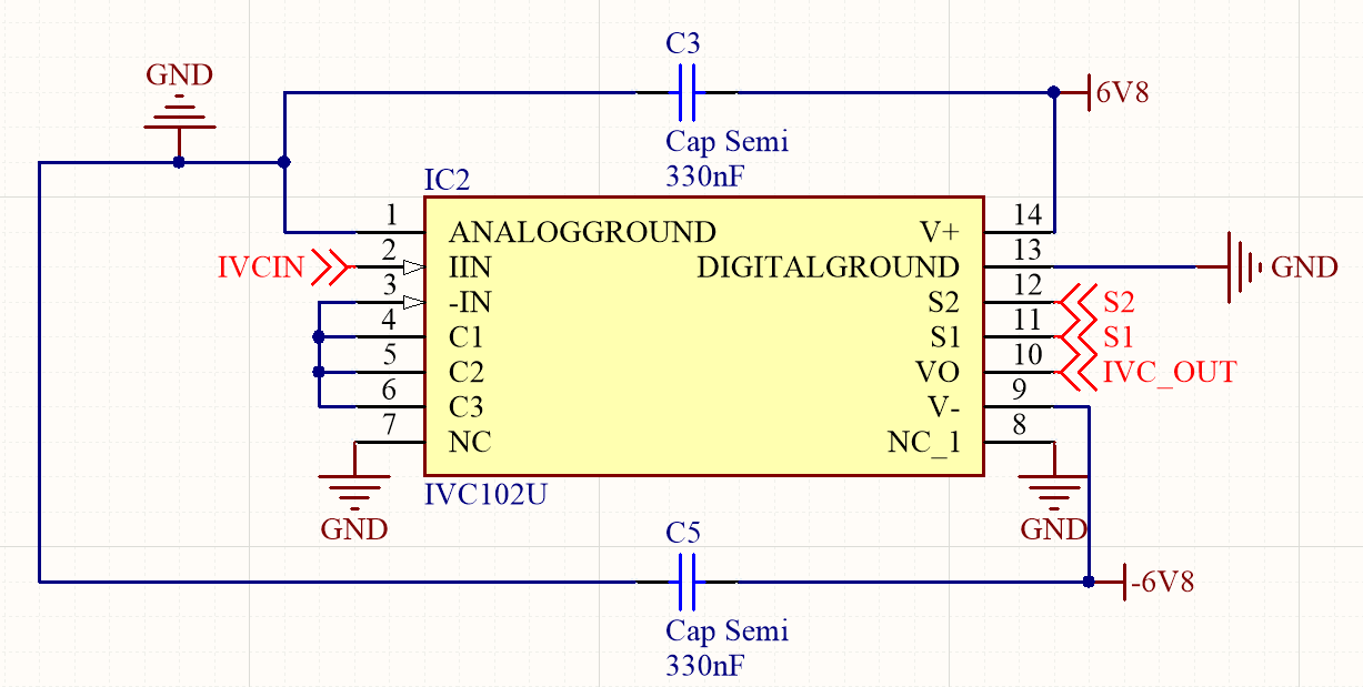
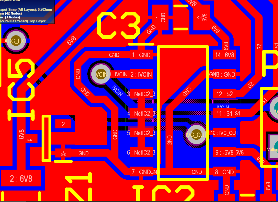
I would like to say that in all related cases the conditions for the input were maintened constant. Also, I will atach the squematic of my circuit, as well how the tracks are routed in the PCB. Can someone give me a light? This behaviour is introducing a big error in my project.

  • Hi,

    What is the light source used for this test and how is its stability?

    In the video I see S1 signal moving in addition to the output. Can you trigger on the S1 signal so we can check that it is constant and see variation of output relative to it?

    Best,

    Alex

  • Hi Alex,

    I dont know if I understand your question right, but for the electrical supply in the IVC, I'm using a voltage source (Agilent U8032A +-12V) that is directly connected to my network.

    I have tried to do what you have asked to me, it's the video 3. The chanel 4 (green) is applied to pin 14 (V+).

    I also did a video that show this same pin (14) in the minimum seconds/division that my osc can get (5nS), because what I thought you were trying to mean is that the voltage source is introducing noise in the supplies. And maybe, in this way, you could check it better.

    Is there any further detail that I could give to you?

    Thanks for the answer,

    Gabriel Santos