This thread has been locked.

If you have a related question, please click the "Ask a related question" button in the top right corner. The newly created question will be automatically linked to this question.

IWR6843: Measure Tx reflected power using mmWave Studio

Part Number: IWR6843
Other Parts Discussed in Thread: MMWAVEICBOOST, ENERGYTRACE, , AWR6843ISK,

Hi,

We are using the IWR684 ES2 chip in our product and we were informed that now it includes directional couplers in the Tx paths, and thus it would be possible to get data for forward- as well as reflected-power. As we know, this feature is only available in mmWaveStudio.

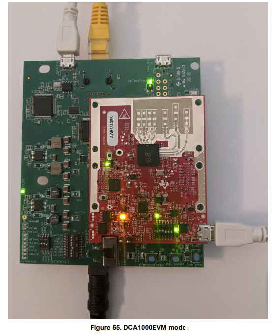
Our radar board can be connected to DCA1000 through 60-pin high-speed connector, but it is not compatible with the mmwaveICBoost. Is there any possible way to run mmWaveStudio only with DCA1000 (i.e. without mmwaveICBoost)?

As I see, we are only missing the USB connection from the PC to the XDS110 emulator. I would like to get more information about the usage of XDS110 in our case. Can we skip it and connect (directly or through DCA1000) from PC to IWR6843? Is the EnergyTrace feature in the XDS110 is used or only the JTAG? 

Best regards,

Yasser

Yasser

  • Hello Yasser, 

       Yes, IWR684 ES2 would support the directional couplers. It is part of monitoring API. Currently monitoring API firmware is under development would be available 2nd half of this year.  

    Once firmware is avaiable you could make use of below API from the SDK.


    For the directional couplers could be used from the SDKs mmWave link functions. 

    Its included in Tx ball break monitoring APIs 

    On the EVM side connecting to directly to DCA1000:

    We have launched new AWR6843ISK EVM which could be directly connected to DCA1000 without using MMWAVEICBOOST board.

       https://www.ti.com/tool/AWR6843ISK

    As shown below:

    For the IWR6843 devices also this EVM would be available by next month. Not for the reference you could use AWR6843ISK hardware (Schematic and Layout would be available in the above link) 

    For more details you could refer to the below EVM user-guide.

    https://www.ti.com/lit/ug/swru546c/swru546c.pdf

    In XDS110 only JTAG is used energy trace is not yet supported on mmWave devices. 

    Thanks and regards,

    CHETHAN KUMAR Y.B.

  • Hi Chethan,

    Thanks for the info. Regarding the second part, we can't use the TI EVM since we have our own module, which can connect directly to the DCA1000.

    What we miss to use mmWave Studio is the XDS110 connection. Since you are saying that only the JTAG is used in the XDS110, would the mmWave Studio works if we connect directly from PC to the JTAG pins on IWR6843 through USB, instead of XDS110?

    BR,

    Yasser

  • Yasser,

    Your above question is not very clear, However let me try to clear your doubts:

    mmWave studio doesn't use the XDS110 connection or JTAG connections, However mmWave studio needs UART Ports (RS232 Tx and Rx) lines for the firmware download. This need to be connected to DCA1000 FTDI's UART ports.  

    If you follow the pin-out of the DCA1000 connector on the IWR6843ISK board then you could connect to mmWave studio directly. 

    Sorry, in the above post image didn't come correctly, I'm re-posting the images.

    You could refer to the schematic and Layout from the below link

    https://www.ti.com/lit/zip/swrr164

    https://www.ti.com/lit/zip/swrc355 

    Thanks and regards,

    CHETHAN KUMAR Y.B.

  • Chethan,

    As I can see in this video (https://training.ti.com/dca1000-training-video), the first USB is connected to DCA1000 for FTDI interface, while the second USB has to be connected to xWR EVM or mmWaveICBoost for XDS110 interface. And as stated in mmWave Studio user's guide (page 10), "The mmWaveStudio should be connected to COM port numbered alongside the name XDS110 Class Application/User UART". This is needed for downloading the firmware through the RS232 connection as you mentioned.

    In our case, we don't have the XDS110 interface and we are not able to use xWR EVM or mmWaveICBoost. Is there any other way to connect mmWave Studio to be able to detect the COM port and connect RS232 under the "RS232 Operations" option?

    Best regards,

    Yasser

  • Yasser,

          RS232 Tx and Rx is must for downloading the firmware into the device in SOP2 mode for the mmWave studio connectivity. If this provision is not provided in the hardware there is no easy way to connect. 

    You may have to blue-wire XDS110 on the mmWaveICBOOST (Disconnecting the lines which goes into the device) or any other EVM which provides USB to UART interface which exposes virtual com port. This COM port number need to be provided in the mmWave studio in SOP2 mode.  

    For mmWave studio connection you must have 1) RS232 TX and Rx lines 2) Reset line 3) SPI lines 4) SOP lines 5) LVDS lines provisions need to be provided, Otherwise interface will not work. 

    Thanks and Regards,

    CHETHAN KUMAR Y.B.