Other Parts Discussed in Thread: TIDA-010022, MMWAVEICBOOST, , CC3235S, SYSCONFIG, AWR1843BOOST
I looked at document TIDA-010022 from TI, but there's no source code of it. After reading, I wanna ask:
1. wifi module in that document is CC1352. In order to communicate between IWR6843 & CC1352 via UART, both modules must modify some parts. Do I need to modify in case I connect IWR6843 & CC3235 via UART? If yes, which part do I need to add/remove? In the document, it mentions MMWAVEICBOOST needs to add R81, R122 but doesn't say which value of resistor I need to use. Please tell me in details in case I use CC3235.
2. on CC1352, it must remove SMA connector before connecting to IWR6843. How about CC3235?
3. on CC1352, it must removethe following jumpers: "5V", "3V3", "RXD", and "TXD" and switch the XDS110 power jumper to "Extern" Power. On CC3235, I don't see 3V3 jumper. Is it VBAT or BRD jumper? Do I have to remove both VBAT & BRD jumper?
4. How to switch XDS110 to Extern Power?
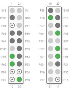
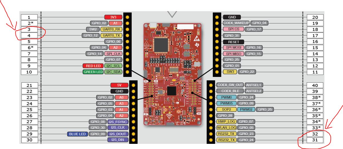
5. Which pins do I need to connect for UART communication? As I understand, connect P1.3 on CC3235 to pin 5 of J5 connector and connect P1.4 on CC3235 to pin 7 of J5 connector on MMWAVEICBOOST, right?
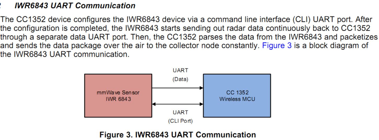
6. As in the photo below, please explain the difference between UART (data port ) and UART (CLI port). As I know, IWR6843 MMWAVEBOOST EVM and CC3235 only have 1 USB port. How can they communicate via 2 separate UART port?
In short, please give me instruction with schematic diagram for wiring between IWR6843 & CC3235 via UART, resistor value for hardware modification on 2 modules, ect...