This thread has been locked.

If you have a related question, please click the "Ask a related question" button in the top right corner. The newly created question will be automatically linked to this question.

MMWCAS-RF-EVM: What's the purpose of the test source case in mmwave studio ?

Part Number: MMWCAS-RF-EVM
Other Parts Discussed in Thread: MMWCAS-DSP-EVM, , TDA2

Hello, I have a question now. 

What's the purpose of the test source case in mmwave studio ?

I mean in the the Cascade_Configuration_TestSource.lua file, the chirp parameters are true.

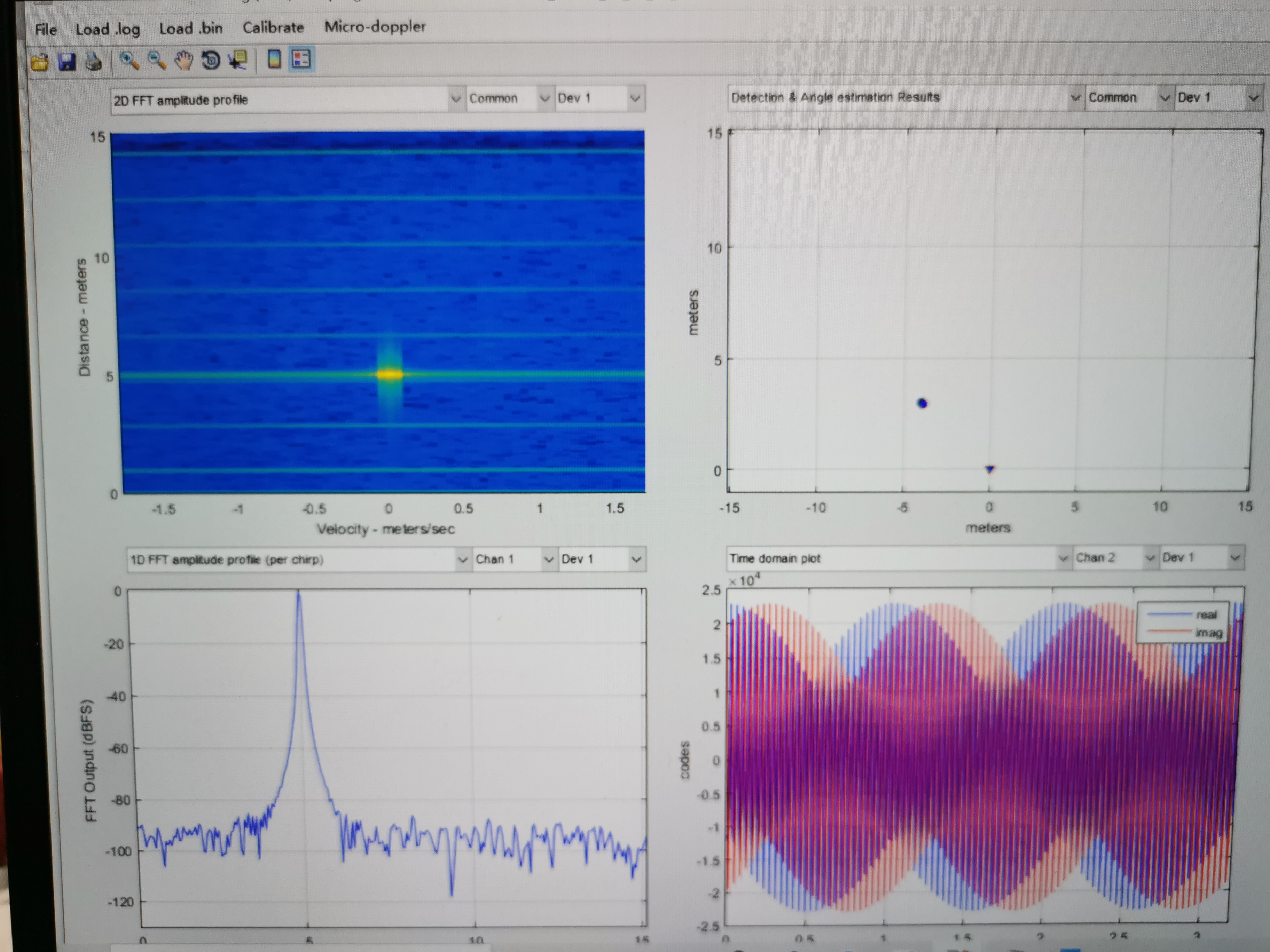
However,  the script as follows seems to construct only a fake target---- an object at about 5m which is non-existent.

Can the test source case serve as a selftest process to prove that the EVMs (MMWCAS-RF-EVM and MMWCAS-DSP-EVM)  work well with basic configurations  in actual environments ???

If not , please help me to provide a selftest method to verify the basic flow because the echo signals can not show the actual targets in my own test.

---------------------------------------------------------------

if(test_source_enable == 1) then
    
    if(RadarDevice[1] == 1) then
        -- Object at 5 m with x = 4m and y = 3m
        if (0 == ar1.SetTestSource_mult(1, 4, 3, 0, 0, 0, 0, -327, 0, -327, 327, 327, 327, -2.5, 327, 327, 0, 
                 0, 0, 0, -327, 0, -327, 327, 327, 327, -95, 0, 0, 0.5, 0, 1, 0, 1.5, 0, 0, 0, 0, 0, 0, 0, 0)) then
            WriteToLog("Device 1 : Test Source Configuration Successful\n", "green")
        else
            WriteToLog("Device 1 : Test Source Configuration failed\n", "red")
            return -3
        end
    end
-----------------------------------------------------------------
  • Hi,

    The test source is useful to simulate the presence of an object.

    It can be used to validate the operation of a radar system

    Thank you

    Cesar

  • Hi, Cesar.

    Now the test source case works well and I can see  the 1D and 2D

    FFT amplitude profile clearly with the object at about 5m.

    However, in my own test indoors, 

    no matter if I put a corner reflector at about 5m or not,

    the 1D and 2D FFT amplitude profile results both can NOT show 

    an object like the test case. In fact ,there are almost no  differences.

    TX beamform and MIMO examples both failed to display the object .

    Maybe there is something wrong with my hardware or software configurations.

    It really freaks me out.

    Please help me.

  • Pic .1 is with a corner reflector.

    Pic.2 is without a corner reflector

    Pic.3 is the test source case.

    Pic .4 is with a corner reflector.

    Pic.5  is without a corner reflector.

    As far as I am concerned ,there is no much difference between the two cases(with and without a corner reflector).

    Please help me.

  • Hi Shengxiang, 

    Have you already run the MIMO virtual channel calibration? The angle spectrum will be very distorted unless you are compensating for the phase variation between all virtual channels. The mmwave studio cascade user guide section 8.3.1 walks users through how to perform a MIMO calibration for the system. 

    Also, the noise floor on your measurements looks kind of high. Can you make sure that the raw data looks reasonable? There is a known bug in the TDA2 capture card software which pretty consistently corrupts the first frame of data. Do all frames look similar for the target/no-target scenario?

    Please let me know if that helps. 

    Thank you,

    -Randy

  • Thank you , Randy.

    1)  I ran the MIMO calibration code and got my own calibrateResults_high.mat,

    then put it in both of the  MIMO and TX beamform folder.

    The picture above shows the corner reflector(with very very huge RCS) was detected.

    However, there are no big  difference for my own test.

    Please see the thread here

    e2e.ti.com/.../914568

    Now the problem is that only the corner reflector with very very huge RCS could be detected.

    But other metal objects, small corner reflectors or human body all failed to be detected in TX beamform or MIMO mode.

    I'm confused by the result.

    2)  The cascade_TxBF_signalProcessing.m 

    " for frameId = 2:numValidFrames "

    means that the frames are processed from the second frame.

    So it seems that the frame processing is OK.