This thread has been locked.

If you have a related question, please click the "Ask a related question" button in the top right corner. The newly created question will be automatically linked to this question.

IWR1443BOOST: calibration of the Rx channel phase offset

Part Number: IWR1443BOOST
Other Parts Discussed in Thread: IWR1443,

Hi,

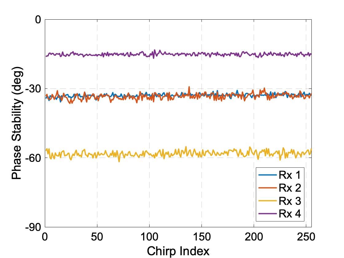
I have been using the IWR1443 BOOST with the DCA1000 data capture board. I was able to obtain the raw ADC samples (both I and Q) using the mmwave studio. When I was looking at the data post processing results, I notice that there is a phase offset between the phase stability plots. In a stable environment, the phase stability for each channel is a relatively flat curve, but the 4 such curves from the 4 Rx channel in the same run are "offset" by a constant phase value, and this phase value seems to change everything the device is re-booted/power-cycled.

If I would like to process the IQ data offline to get other information - for example the angle of arrival (AoA) of the reflector - how should I calibrate out this offset when performing the angle-FFT across the Rx antennas? Also, are there any reference doc/code that explains how the AoA in the mmwave studio postproc tab is obtained from the raw IQ binary data?

Thank you very much,
TC

  • Hi TC,

    Would you be able to post some pictures or data of this?

    Regards,

    AG

  • Hi AG,

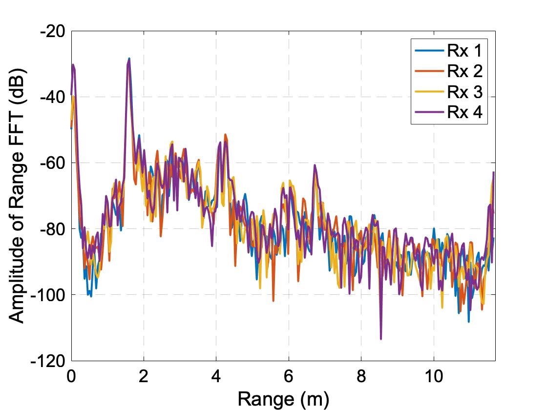
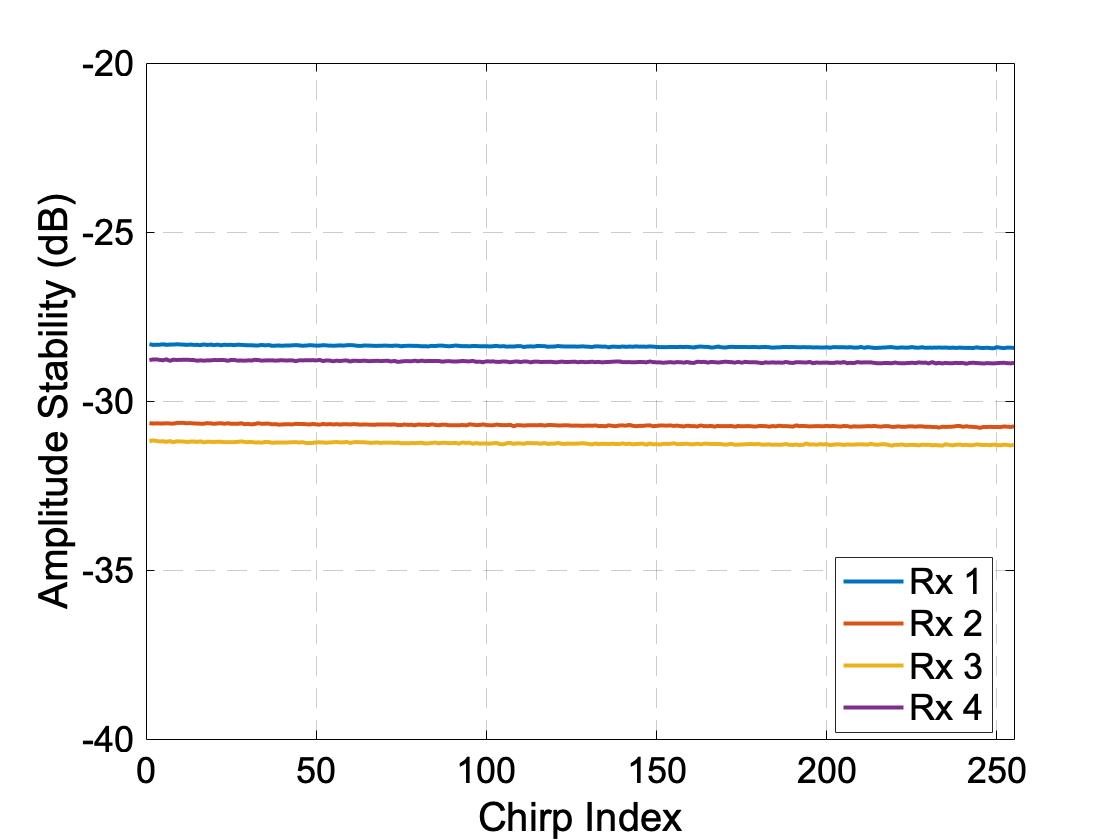
    I am attaching three plots below which are all generated using the IQ data captured by the DCA1000 data capture board. In this experiment, a reflecting object is placed at ~1.5m away right in front of the object with AoA of 0 deg (as you can see from the range-FFT plot for each of the 4 Rx channels). One chirp consists of 256 IQ samples, and one frame (for the amplitude and phase stability plots) contains 255 chirps. 

    As you can see from the phase stability plot, there is a relatively constant phase offset between the Rx channels, and the gaps are not evenly distributed (which I would assume it's the case since the reflecting object is placed at AoA of 0 deg.

    How can we calibrate out this phase offset between different Rx channels? Or in other words, what do I need to do to generate the range-angle plot using angle-FFT? I understand that we should take the 4 peak FFT values from the range-FFT results and perform the angel-FFT across them. But this is only a complex-valued vector with 4 elements, and how should I perform the angle-FFT and possibly with the phase calibrations? Given that the postproc option in mmwave studio produces the correct AoA, I would assume that some level of phase calibration is performed but I am not completely sure about that.

    Thank you very much for your time and help,
    TC

  • Hi, TC:

    The phase/gain calibration is supported in the SDK OOB demo.  You can find some Doxygen documentation at:

    file:///C:/ti/mmwave_sdk_03_04_00_03/packages/ti/demo/xwr18xx/mmw/docs/doxygen/html/index.html

    Search for "Range Bias and RX channel Gain/Phase Measurement and compensation" for details.   

    The basic idea is that the phase for all TX-RX antennas pairs should be the same when the target is at angle of zero (on both azimuth and elevation direction).  However, the measured phase is often not the same (just like what you have observed).  So, you just needs to compute these phase with target at zero angle, and invert these phase for each TX-RX antenna pair to force them all to zero phase.  

    The post processing inside the radar studio does not include the calibration step, because the radar studio do not know the ground truth of the target.   If you see the target angle is estimated correctly.  Then it is possible that the angle estimation is not bad without phase/gain calibration for your EVM board.

    In terms of how to estimate angle of arrival, you can find some Doxygen documentation at:

    file:///C:/ti/mmwave_sdk_03_04_00_03/packages/ti/datapath/dpc/dpu/aoaproc/docs/doxygen/html/index.html

    Best,

    Zigang   


  • By the way, you can also find training material on the angle of arrival estimation at:

    https://training.ti.com/intro-mmwave-sensing-fmcw-radars-module-5-angle-estimation?context=1128486-1139153-1128546

    Best,

    Zigang

  • Thank you very much Zigang for your response. A few follow up questions:

    - Regarding the calibration process, where should I put the line "measureRangeBiasAndRxChanPhase 1 X D" if I am using the mmwave studio? Also, let's say if my X is 1 meter, usually how should I select the value of D?

    - What I also observed before that after each power cycle, the phase offset seems to be randomly reset. If this is true, does it mean that the range bias and phase offset need to be performed everytime the IWR1443BOOST and DCA1000 are powered up?

  • Yes I have watched that training video before and I think I understand the concepts. My real question is how is the angle-FFT implemented (which I asked twice above...)

    Let's say I am using 1 Tx and 4 Rx, after the 2D-FFT on each Rx channel, I will get 4 peak values to form a 1x4 complex-valued vector. Based on the video, it seems like I will just need to do a 4-point FFT on this vector, is that right? Or otherwise, how should I chose the FFT size for the angle-FFT? I also read from other places that the steering vector needs to be used, what is the detailed method for computing the AoA?

  • HI, this calibration procedure is only supported in SDK out of box demo and visualizer.   

    If you want to use radar studio instead, then you can do raw data capture with a corner reflector placed in a clean experiment at zero angle.  Then you can derive your own phase compensation coefficients.

    It is OK to have different phase offset after power cycle, as long as the relative phase difference between the antennas are the same.   With power cycle, after compensation, all the phase may not go back to zero, but they should become the same angle (with some error).

    Best,

    Zigang

  • Hi, 

    Usually we would like to have the large FFT size so that when you search the peak on the angle spectrum (the power of angle FFT output), you get better angle accuracy.   

    If the the training video and Doxygen documentation does not give you enough information, for more complete and detailed understanding of angle estimation, you can either go through the source code line by line or you can go through the literature search to get the understanding.   

    Best,

    Zigang