This thread has been locked.

If you have a related question, please click the "Ask a related question" button in the top right corner. The newly created question will be automatically linked to this question.

awr1243p:The antenna transmits signals at the same time or time-sharing

Other Parts Discussed in Thread: MMWCAS-DSP-EVM, MMWCAS-RF-EVM
Hello,
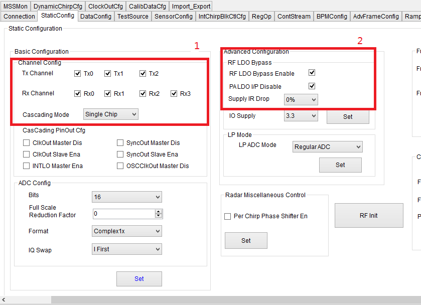
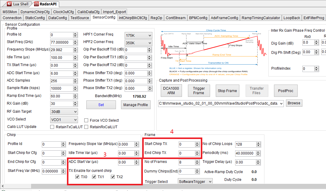
I have used several single-chip AWR1243 radars from TI, I am using MMWCAS-RF-EVM+MMWCAS-DSP-EVM with mmwave studio. And I have some confusion about cascading devices setting up multiple antennas in mmwave studio to transmit signals simultaneously and separately, so please answer them. First, when I check 3 transmitting antennas at 1 in the first picture, then check RF LDO and PA LDO at 2 (the manual says it is to protect the radar chip), then I check 3 at the second picture Check the 3 transmitting antennas, then select 0 and 11 for Start and End at 4, respectively. Will this parameter(Other parameters are set according to the parameters of using single chip 1243) setting enable 3 transmitting antennas of each 1243 to transmit signals at the same time, a total of 12 antennas transmitting signals at the same time? If so, then I would like to ask
1. Is it possible to select one less antenna based on the above parameter settings for two transmitting antennas to transmit signals at the same time?
2. In addition, how can I set the parameters to realize the antenna time-sharing transmission signal?
3、When I use single-chip AWR1243+DCA1000 for data collection, I will check 2 transmitting antennas in 1 place of the first picture, 4 receiving antennas, uncheck in 2 places, and then 3 in the second picture Select two transmitting antennas at the location, and unselect at four locations. Does this parameter setting mean that when I use a single chip 1243, the two transmitting antennas also transmit signals at the same time instead of time-sharing?
4、When setting parameters in mmwave studio, what is the standard to distinguish between multiple antennas transmitting signals simultaneously or time-sharing signals?
  • Hello,

    As far as I've understood, you want to achieve time division multiplexing between antennas. You can refer to the below document as a heads up :

    https://www.ti.com.cn/cn/lit/an/swra554a/swra554a.pdf

    In addition to this, we have example MIMO scripts in the mmwave studio package to help you get started on this.You can find them here : ..\mmwave_studio_<ver>\mmWaveStudio\Scripts\Cascade

    Please find the answers to your questions below:

    1. Is it possible to select one less antenna based on the above parameter settings for two transmitting antennas to transmit signals at the same time?

    <Ishita> Yes, you can.

    2. In addition, how can I set the parameters to realize the antenna time-sharing transmission signal?

    <Ishita> If have already pointed you to some scripts and documents which could help you achieve that.

    3. When I use single-chip AWR1243+DCA1000 for data collection, I will check 2 transmitting antennas in 1 place of the first picture, 4 receiving antennas, uncheck in 2 places, and then 3 in the second picture Select two transmitting antennas at the location, and unselect at four locations. Does this parameter setting mean that when I use a single chip 1243, the two transmitting antennas also transmit signals at the same time instead of time-sharing?

    <Ishita> Yes, with that single chip setting, both the TX are transmitting at the same time.

    4、When setting parameters in mmwave studio, what is the standard to distinguish between multiple antennas transmitting signals simultaneously or time-sharing signals?

    <Ishita> The Tx channel settings in the "StaticConfig" tab (i.e. "1" in your first picture) basically indicates the number of Tx you want to use in your entire experiment. This is done to enable Tx LDOs by the firmware. You may be just using one Tx at a time, but for that Tx to transmit, you have to first enable it here.

    Time division multiplexing  can be achieved in the "sensor config" (i.e "3" in your second picture), by allocating different chirps to different TXs.

    I hope I was able to solve your query.

    Regards,

    Ishita

  • Hello,Ishita

    I am very happy to receive your reply. After I read your reply carefully, I have an understanding of time-sharing and reuse. I will implement it later. I also want to make sure that if I want to set up 3 transmit antennas to transmit signals at the same time, I should check the 3 Tx in 1 place in the first picture, then check the RF LDO and PALDO in the 2 place, and then in the second picture Check 3 TXs in 3 place, and finally select 0 for start and 11 for end in 4 place. The other parameters are set according to the parameters of single chip 1243, is that correct?

  • Hello,

    Yes, you are right.

    Regards,

    Ishita

  • Thanks for your help,Ishita.

  • Hello,Ishita

    As we talked about yesterday, today I conducted a test with three antennas transmitting signals at the same time, but there was still an error. I think this is not a new problem, so I did not open a new problem, but continued the problem.
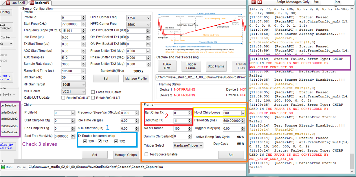
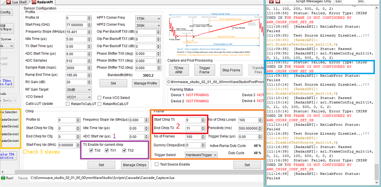
    As shown in the picture, when I set the parameters to (0, 11, 500, 100, 484.8) in the Frame box, I selected three slaves, then selected Hardware Trigger, clicked set, and the result was reported as error in the output window. So the same error is reported many times because I tried multiple sets of different parameters. Picture 2 is a set of settings with a small number of pulses, but the same error is still reported. I'm sure that all operations before this setting are without problems, and no errors are reported.
    In addition, I have a few questions to ask you:
    1. For the setting at one place in the picture, check the three transmitting antennas to enable them to work at the same time?What is the significance of this setting?
    2. For the settings at 2 in the picture, when I used the single chip 1243 (1243+DCA000/TSW1400), I never set these two parameters, so the default values ​​of these two parameters are 0, Does this mean that I have only used one antenna all the time? Even if I checked two antennas in Static Config.
    3. For the settings at 2 in the picture, when I set Start Tx to 0 and End Tx to 11, I found that the value of the frame period needs to be multiplied by 12 on the original basis (for example, the previous frame period is the pulse width* The number of pulses +300us + a pulse width = 40ms, but now it needs to be set to 40 * 12 = 480ms), why should it be multiplied by 12? The 12 antennas I set are transmitting signals at the same time. The time required should be equal to the time required for one antenna, that is, 40ms, but the fact is that 480ms is required. Why?
  • Hello,

    As I can see in the chirp Config, you have only configured one chirp i.e chirp 0, but while issuing the API for frame, you're putting the "end chirp Tx" as 11. You can only configure those chirps in the frame config for which you have already issued a chirp config API. The error you got, is also stating the same fact.

    If you want to configure 11 chirps, select "end chirp for cfg" in the chirp config window as 11 and then try again. 

    Please refer to the mmwave Interface control document and this document for better clarity on configuring chirp and frame profiles.

    Regards,

    Ishita


  • Thank you very much,Ishita.

  • Hello,Ishita

    Regarding the question I consulted with you before, I had another question when researching related documents. I think this is a sub-question of the big question I asked, so I didn't choose "Ask a new question". If I did something wrong, please let me know and I will choose "Ask a new question" next time.
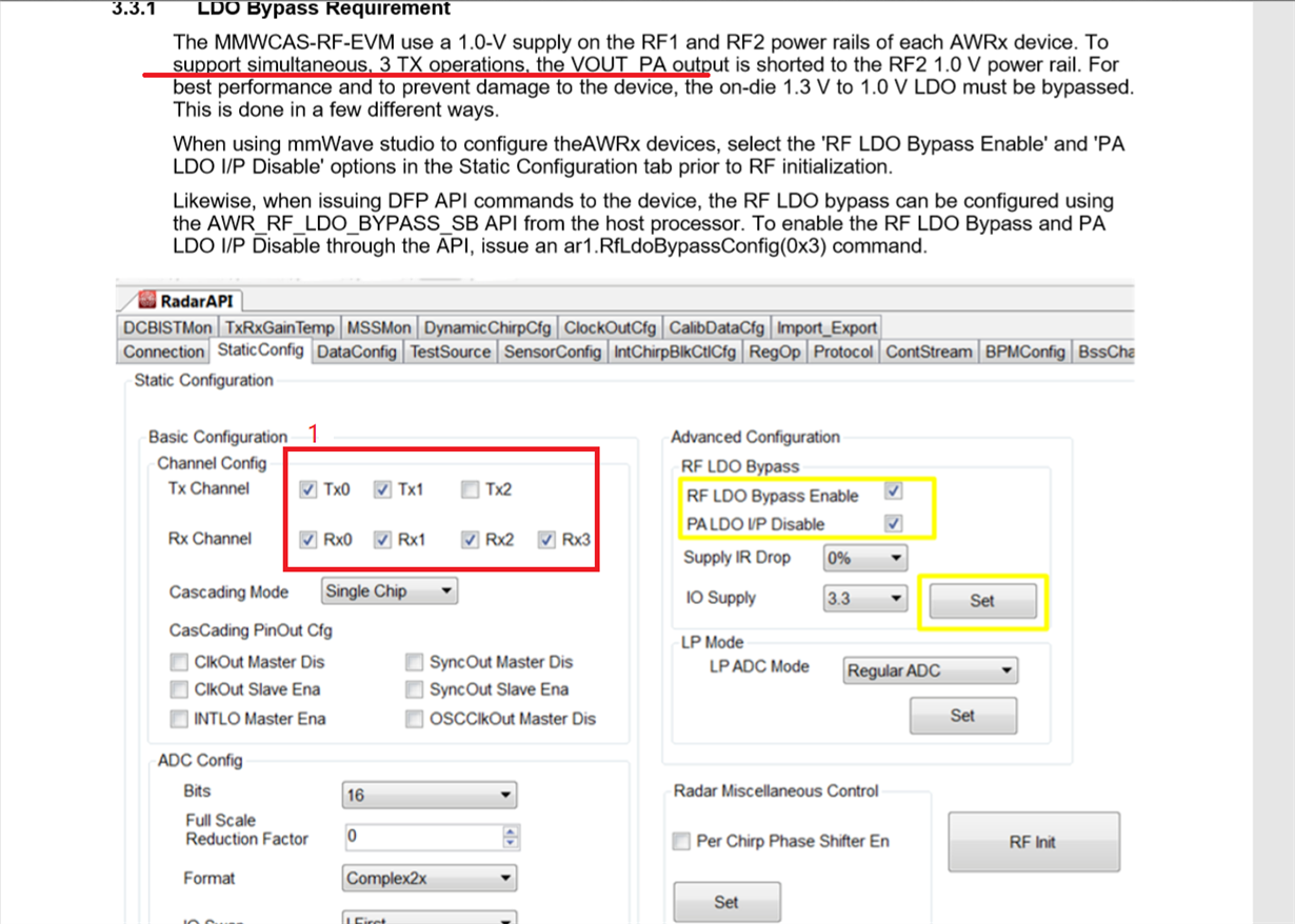
    This is the case, as shown by the red mark in the attached picture, the document MMWCAS-RF-EVM.pdf indicates that when three antennas are working at the same time, in order to protect the device, "RF LDO Bypass Enable" and "PA LDO I/ P Disable" need to be checked, I want to know if I select 3 TXs at 1 in the picture, but only one antenna is enabled in the chirp box of the sensor config, according to this configuration, only one antenna transmits signals instead of three The antennas transmit signals at the same time. In this case, do you still need to check "RF LDO Bypass Enable" and "PA LDO I/P Disable"? For MMWCAS-DSP-EVM+MMWCAS-RF-EVM, no matter how to configure, you must check "RF LDO Bypass Enable" and "PA LDO I/P Disable" to protect the device?

  • Hello,

    Yes, as it is mentioned in guide, MMWCAS-RF-EVM uses a 1V supply on RF1 and RF2 rails for a simultaneous 3 Tx operation (the connections are already made in hardware). Hence you have to enable the corresponding check boxes.

    Thanks!

    Regards,

    Ishita