This thread has been locked.

If you have a related question, please click the "Ask a related question" button in the top right corner. The newly created question will be automatically linked to this question.

PGA970: Wave Generator not working properly (PGA970EVM)

Part Number: PGA970

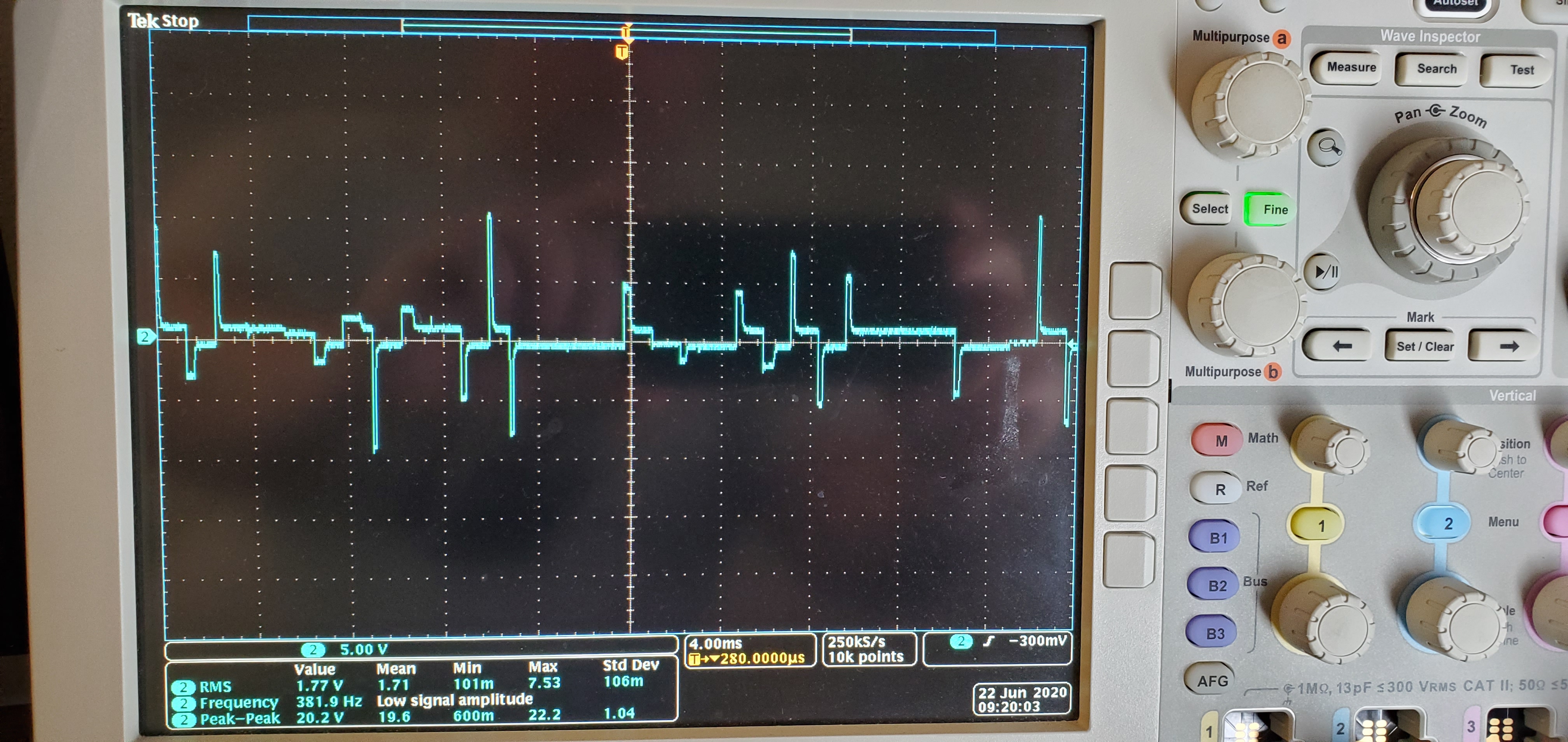
When I first got my PGA970EVM working using only the GUI (I have yet to alter any firmware), I was able to create the needed 3kHz 5Vrms excitation signal for my LVDT.  Unfortunately, I don't have a picture of it working because I didn't see a need to do so when it was working as expected.  Recently, I swapped out the LVDT for another similar LVDT.  I am not sure what happened, but this is the waveform I get now.

It also appears that ADC 2 is no longer working.  I can get small signal readings from one of the secondary's through ADC1, but I get no reading at all from ADC 2.

I'm thinking that there was something wrong with the wiring of the new LVDT or it possibly was defective in some way or there was an ESD event.  In any case, there was no protection on any of those inputs/outputs and now my board is now, just a noise generator at best and garbage at worst.

Any thoughts?  Here are the settings with no jumper changes from delivery.

  • *Update - I checked the LVDT on our LCR meter.  It appears to be fine - nothing wrong with it.

  • Hi Daniel,

    If you read the full contents of the registers on the Low Level Configuration page, do you see the expected values? Or does it look like everything gets set to the same incorrect value?

    Can you check the AVDD and DVDD voltages on the EVM? They should be 3V and 1.8V respectively.

    Regards,

  • Just checked DVDD (1.885V) and AVDD (2.985V) with my Fluke.  Also, the Low Level Configuration is reflecting the GUI settings. 

    Register LVDT_OP_CTRL:

    DAVCM_CTRL: 0.86;

    DIFF_VOCM_CTRL 1.5;

    GAIN_CTRL 1.18;

    SKIP_FILTER Disabled

    Register WAVEFORM_TABLE_LEN: 0x52

    Register WAVEFORM_GEN_CTRL:

    WAVE_EN Enabled

    WAVE_STATUS Disabled (this status register doesn't appear to be attached in the base firmware - it never becomes enabled even when the waveform generator is running like now)

    The waveform looks a bit different today from the previous picture, but it is still garbage.

  • Hi Daniel,

    Considering that the waveform was working before with another similar LVDT it is unlikely to matter, but does the waveform look better when there is no LVDT connected? Does anything change when you adjust the waveform settings? Can you also measure the waveform at the PI pin? How does it look there?

    Are you able to adjust any of the other device settings properly? For example, can you send a fixed code to the DAC, measure the output, then send a different code and measure a change?

    Regards,

  • Yes.  I am able to connect the DAC through the loopback to the ADC's and measure changes when I command them in gui from the DAC menu.  The only thing not working is the Waveform generator.

    As for the signal coming from the waveform generator, Yes, there is a difference when the LVDT is connected.  I can even see small changes as I pull the core in and out when it is near the extremes (outside of normal measurement range).

    The board is just scrap.  There is no hardware protection on it.  Again, I am flabbergasted at this.  I can't get a prototype build off my desk without some basic ESD/EMI protection on outside connections.  No one wants to have to change out a proto-board because a technician accidently zapped it with ESD between tests causing the entire set of tests to start over with a new board.  Yes, I argue that they are the same board and the previous tests should stand, but that's not how the procedure is written or something like that.  

  • Hi Daniel,

    Can you please clarify your last response? It sounds like you have seen this on multiple PGA970EMVs, or was it just the one EVM where the waveform generator became faulty?

    Also, were you able to test at the PI output? You can look at this at either TP16 or TP19. This can help determine if the problem is with the waveform DAC or the PGA amplifying the DAC output. Additionally, are you using the external amplifier circuit on the EVM to gain up the LVDT supply? Does J2 have pins 1-2 shorted, or pins 2-3, and is it the same or different from J7?

    Regards,

  • Scott,

    To clarify, I have multiple LVDT's - not PGA970EVM's.

    As for the test points-

    1. You cannot isolate the DAC generation from the chip from the amplifier as they are connected, at the very least, at the input pin (through a 0.47uC cap and 31.5k resistor).  

    2. I have checked these test points (TP 16 and TP 19)  and it is the same as if you set the jumpers to not use the amplifier (J2 and J7 set to short Pins 2 and 3)

    3. The amplified signal looks like an amplified version of the non-amplified signal with the, in general, correct voltage range with the exception of aliasing spikes.

    I have considered removing the amplifier from the board (I have the equipment to work on boards), but came to this forum first as customer support indicated that I should.

    BTW, that is an expensive Op-Amp and totally not necessary for that circuit, but, hey, better to err on the side of caution! (I've used similar circuits to excite resolvers with the same variable range of frequencies).  However, I did actually use the BJT amplifier portion and not just the op amp output.  Also, I think the resistors on the schematic portion of the BJT amplifier portion are incorrect.  Using SPICE simulation, that part of the circuit does not work correctly until you fix them (I changed them to what I've used previously and it worked fine - including changing the gain on that Op Amp).  Then again - the expensive op amp and that gain take away the need for the other amplifier (should have just taken* it out of the schematics it would have saved confusion).

    As for the jumpers, all jumpers are set per factory baseline.  The damage occurred while the excitation was connected through the amplifier (J2 and J7 set to Pins 1 and 2 shorted).  This should preclude damage to the PGA970's output, but I can't prove that with the amplifier in the circuit, and I have an odd feeling that it is damaged in any case.

    Should I remove the op-amp to check the PGA970 signal to see if it is damaged?

    *edited took to taken - sounded horrible

  • Hi Daniel,

    Thanks for the detailed information. One way that you can isolate the waveform DAC output without removing the amplifier would be to remove R23. From there you can measure at TP16 and get the direct single-ended DAC output with it disconnected from the internal PGA. I would start with that before removing the opamp since it is simpler and there's less chance to damage the board in the process.

    If that looks good, then either the internal PGA could be damaged, or the opamp could be. I would keep following the signal path one component at a time, and feed a known signal into the PGA at TP19 (with the DAC output still disconnected by removing R23) and measure the output at PxA. You could remove C4 and C8 to completely disconnect the opamp circuit from the internal PGA if you like


    Regards,

  • Just got an email saying TI thinks this issue is resolved - In what way or form is this issue resolved?  I bought a $200 development board that broke when I changed and input because you felt it was too costly to have an ESD protection on outside connections?

    Are you guys going to replace this board or not?  It is unusable.  

  • Hello Daniel,

    The thread has never been marked "TI thinks resolved," and I don't consider this resolved, so I'm not sure why that email would have been sent. If you ordered your board through a distributor, then you can submit a return through them to get a replacement board. If you ordered from ti.com, or if you have any trouble at all with your return through the distributor please visit the TI customer support center: https://ticsc.service-now.com/csm

    Regards,

  • Never buying TI again.  I was told to come through here by a TI representative to decide that the board was broken and would need replacement.  I’m going with the Analog Devices’ chip for my product.
     
  • Just FYI,

    That is not what your representative told me.  I was informed that I needed to post my issue on this thread to determine that the board was broken to have it replaced.  Also, this fault is a DESIGN fault as I KEEP POINTING OUT! How did this get past a single review let alone through product review?  Is this the quality to be expected out of TI?  I have not had a good experience dealing with TI.  There are 0 representatives for your products in my area.  The one who used to represent TI was told that you all are pulling out and just going to use Mouser and Digikey or something like that.  So, no, my representative didn't get the board for me or I would have had 3 replacements with their apologies by now instead of spending weeks discussing this with you on a forum.

    If this board is not going to be replaced because, as you already know no matter how much you keep trying to troubleshoot it to be something else, it is broken and cannot be fixed.  It was obvious from my first oscilloscope picture.  A damaged op-amp could not cause that signal.  Each part of that signal was properly amplified.  That is a broken DAC.  This chip is supposed to cost $11, but the development board was $189 WTF.  The Analog Devices equivalent (not quite equivalent as theirs is no programming and works without any programming work beyond circuit work).  Their chip, in low quantities costs almost $40, but their development board is $89.  

    So, as I understand it, I have, basically, a broken toaster that is never going to be replaced so that I can actually test your device for my product.  If this is true, then I won't be able to use your device in my product development.  I'm sorry.

  • Hi Daniel,

    I'm in agreement that the board or the PGA970 device itself is damaged. If the representative you spoke to required you to get confirmation of a damaged EVM, then please refer them to this post and to me if they will not honor your request for a replacement.

    Regards,

  • Hi Daniel,

    Is it alright if I contact you through email to discuss sending you a replacement directly?

    Thanks,

  • Scott,

    Feel free to contact me directly.  I would have accepted that over the forum if you wanted with the troubleshooting.  I look forward to hearing from you.

    -Dan