This thread has been locked.

If you have a related question, please click the "Ask a related question" button in the top right corner. The newly created question will be automatically linked to this question.

AWR1642BOOST: Precision Short Range stationary object detection behind lossy Dielectric medium

Part Number: AWR1642BOOST
Other Parts Discussed in Thread: AWR1642

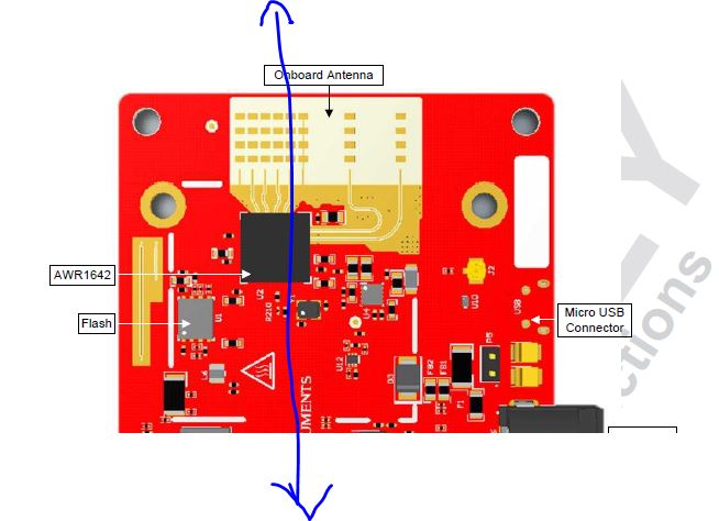
I am using the AWR1642 Boost in an experiment to determine the change in the reflectivity ity (with time) of partially reflective surfaces  along the longitudinal direction of an object in front of the radar. I am using an Ultra Short Range Configuration with a Range  resolution of about 5cm .I am able to get results (laterally  across the outer surface  but not no inner measurement. I am expecting losses so I have varied with the detection threshold  but still  unable to  get the resolution  in the longitudinal direction. The object is stationary and only ten (10) inches from the device so I thought the power should be enough.. I am wondering if anyone has tried an experiment like this and what can I do to get the results in the longitudinal (axial)l direction. I am looking at both the scatter and the range plots

  • Hello Lincoln,

    By longitudinal direction do you mean In the direction along the blue line shown in the below figure?

    The antennas on the 1642boost are all aligned in the azimuth plan, so there is no angle measurement possible  on the elevation plan (in the direction of the blue line). So all the objects in that plan will show up at 0deg elevation itself. In the 1843boost , which has 3 Tx antennas, there is one Tx antenna that is design for elevation plan, so you get some angle on the elevation plan too.

    Regards,

    Vivek

  • Hi Vivek,

    Thank very much  for replying

    I am not, at the moment, concerned with the elevation. I am looking in the azimuth direction with  5 ' Lossy dielectric slabs lined  behind each other (5 cm apart) in front of the EVM. These slabs are somewhat reflective so I trying to find defects in them by measuring their reflectivity. This is in an attempt to test my simulated results. It's good news regarding the I843 as I probably will use this device in the final design. I have been able to get results laterally on the front slab but  nothing from the slabs behind. I have set the range resolution to maximum and expect that I have enough  power  to penetrate  and reflect from at  least the 2nd slab. The idea is that each slab should show as a separate surface so I have set  the range resolution of 0.044M.

    I am trying to find out if the setup is ok or if anyone has tried in-wall measurements looking  for defects  on items behind  each other that are not fully  reflective 

    Lincoln

  • Hello Lincoln,

    If you set a chirp BW of 4Ghz, then you have the best possible range resolution. But the signal level of the second slab will be so much more weaker than the first slab reflection. So getting the  theoretical 4.4mm  range resolution in this case would be very challenging , because the weaker signal might be heavily submerged in the stronger signal. If you look at the 2D FFT plot it might be more clear.  If you move the second slab further away, like  2 -3 Mhz away in IF frequency, does that help detection?

    regards,

    vivek