This thread has been locked.

If you have a related question, please click the "Ask a related question" button in the top right corner. The newly created question will be automatically linked to this question.

PGA302: PGA302 I2C interface

Part Number: PGA302
Other Parts Discussed in Thread: MSP430F5510

Hello

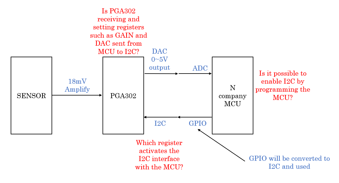
I have a question about the PGA302 I2C feature.

Since the PGA302 GUI Tool cannot be used, I will use it by setting registers in the PGA302 through I2C communication from the MCU.

I found that I2C communication is not activated in the basic communication found in the E2E™ support forums.

What to do if MCU access PAG302 and try to send register
And please let me know what you need to do in MCU or PGA302 to activate I2C interface communication.

Thank

  • Hello Seok,

    I'm curious why you say the GUI cannot be used. Using the GUI is the simplest method to communicate with the PGA302. If you would like to use a separate MCU to communicate with the PGA302, the I2C timing requirements are here:

    Pull-Up Voltage = 1.8V, Capacitance Load on Pin = 100pF, Pull-Up Resistor= 1.3KΩ

    VIH High-level input voltage min 0.7*DVDD V
    VIL Low-level input voltage max 0.3*DVDD V
    VOL Low-level output voltage max 0.4 V
    fSCL SCL clock frequency if M0 frequency is 1MHz  max 800 KBPS
    if M0 frequency is >1MHz max 1000 KBPS
    tSTASU START condition set-up time min 260 ns
    tSTAHD START condition hold time min 260 ns
    tLOW SCL low time min 0.5 μs
    tHIGH SCL high time min 0.26 μs
    tRISE SCL and SDA rise time max 120 ns
    tFALL SCL and SDA fall time max 120 ns
    tDATSU Data setup time min 150 ns
    tDATHD Data hold time min 150 ns
    tSTOSU STOP condition set-up time min 260 ns
    tSTOSTA Time from STOP condition to new START condition At 100KPBS min 4.7 μs

    A description of the command and receive packets for I2C communication with the PGA302 is located in the I2C interface section of the datasheet.


    Regards,

  • Thank you for answering the question.

    I have N company's MCU, so I have no choice but to use this product.
    The reason I can't use the GUI is that it's inconvenient to set up multiple products.

    There are additional inquiries.

    Please refer to the picture below.

    1) Is the MCU programmable with the PGA302 to set registers using the I2C interface? Should I use MSP430F5510?

    2) If the MCU sends data when the master PGA302 is the slave, can the PGA302 receive the data and set the register?

    3) If PGA302 is not the basic communication mode, how to activate I2C?

    please answer about my question.
    Thanks.

  • I have a question after a long time.

    Sorry to keep asking.

    There are additional inquiries.

    I want to set the GAIN value in PGA302.

    I am going to set it up by connecting with PGA302 GUI EVM. Do I need an MCU in the middle to connect with PGA302 and PC?

    I purchased PGA302EVM-037 and I wonder if the PGA302EVM-037 Top Board Sections, PGA302EVM-037 Bottom Board Sections and usb are delivered together.

    Thanks.

  • Hello,

    If you purchased the PGA302EVM, then it includes everything you need to communicate with the PGA302 except for your PC. You do not need an additional MCU.


    If you wish to use the PGA302EVM only as a way to send I2C commands to a separate board, you will just need to wire the SDA and SCL lines from the EVM to your board. Note that you cannot have 2 PGA302 devices on the same I2C bus, so you will have to remove the PGA302 device from the EVM if you want to read back data.

    Regards,

  • Hello,

    In reply to your earlier questions.

    1. The PGA302 always acts as a slave device, and can be configured using any MCU that has I2C protocol functionality.

    2. Yes, the MCU can send commands to read or write to registers in the PGA302.

    3. The PGA302 has 2 modes of operation:

    1. running mode, where the digital interfaces (OWI and I2C) are not active, and the input signals is processed and a voltage output is produced by the DAC

    2. reset mode, where the digital interfaces are active. to switch to reset mode from running mode, you send 0x03 to the micro_interface_Control register. Details of how to structure the I2C command to properly address each register are included in the I2C Interface section of the datasheet.

    Regards,