Because of the Thanksgiving holiday in the U.S., TI E2E™ design support forum responses may be delayed from November 25 through December 2. Thank you for your patience.

This thread has been locked.

If you have a related question, please click the "Ask a related question" button in the top right corner. The newly created question will be automatically linked to this question.

IWR1642: I have a question about PCB manufacturing using IWR1642

Part Number: IWR1642

Hello. I am Terry.
I designed a PCB using the IWR1642 chip.
When designing the PCB, I used the "Rogers4835 Low pro" product.

However, I bought Rogers 4835 Low pro, but H/H instead of 1/H. Because 1/H was very difficult to get.

And I purchased ITEQ180A 28mil core 1/1 products, IT 180A Prepreg 1080 and Iteq 180A 4mil core 1/H.

And although the PCB was manufactured, it was processed with gold plating because it was not possible to do immersion silver plating process.

After that, I downloaded the People count program to the IWR1642 and verified the performance, but it resulted in poor cloud points than the IWR1642 Boost board.

I think that there is three different factors in our PCB compared with 1642 Boost.

1. NOT immersion silver plating (used gold)
2. NOT I/H (used H/H)
3. a litter bit different Via placement, but it is within the error that TI offered (0.1~0.3mm), see attached files

what is the main factor affecting the poor performance of our board? any futher considerations that I don't know?

please let me know...

8865.Design Ref.pdf

  • Hello,

       Is the schematic and layout are the same other than what mentioned above?

    Could you post the schematic and layout?

    Also elaborate performance differences between them?

    Thanks and regards

    CHETHAN KUMAR Y.B.

  • Hi^^ Thanks for your reply

    I leave a reply by attaching a document related to the layer . Also I have questions.

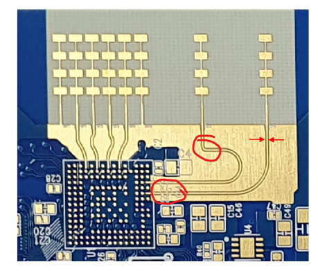
    If the gap between the wiring reaching the TX(RX) antenna and the surrounding ground is close, can performance degrade?

    See page 22 of the attached document.

    Thank you.Layer Check.pdf

  • Hello,

          Yes, if the air gap is lesser or more they will have impact on the matching of the antenna, Matching of the antenna ports are governed by S11 parameters. Goal of S11 parameter to have better than -10dB to get best matching, If this is degraded then full output power from the Tx ports will not be delivered to Antenna and Same case for Rx antenna to LNA ports.

    And dimensions of this is arrived after simulating in 3D Electo-magnetic field solver. If there is a change in that dimensions there would be impact on the S11 parameter, hence correspondingly it would degrade the output power. I you have changed the dimensions then you need to re-simulate in 3D EM solver for Package to board transition, transmission line, Antenna performance and need to confirm the Antenna performance.

    Hence its not recommended to change these values without careful simulations. Recommendation to reuse all the dimensional targets as used in the EVM. 

    Please refer for RF PCB Design, Manufacturing and Validation application report: https://www.ti.com/lit/an/spracg5/spracg5.pdf

    By going through the pdf files there are other issues also noticed:

    1) As you rightly mentioned ENIG surface finish is not recommended, It's lossy at mmWave frequencies.

    2) 90 Deg Bends are not recommended as shown below, slow or larger radius curve bends are recommended. 

    3) There are texts/legends on the RF traces it changes the dielectric constant of transmission line environment and degrades S11.

    Thanks and regards,

    CHETHAN KUMAR Y.B.

  • Thank you for your kind reply.

    I will be helpful for me to design it again.

    One thing, I want check about using I/H of Rogers 4835.

    Already mentioned above, I used H/H. is it OK? or must use 1/H?

    Please let me know.

    Thank you in advance.

  • Hello HWANG YONG,

        Thanks for the acknowledgement, it's recommended to have 1/H.  Half Oz cu on the top surface where antenna are located is a must, and for the ground 1Oz Cu is desirable. This provides lower ground impedance as compared to Half Oz Cu, Also provides better thermal performance for the sensor to spread the heat laterally. 

    Thanks and regards,

    CHETHAN KUMAR Y.B.