This thread has been locked.

If you have a related question, please click the "Ask a related question" button in the top right corner. The newly created question will be automatically linked to this question.

TDC1000-Q1: Received signal very poor or not there at all

Part Number: TDC1000-Q1
Other Parts Discussed in Thread: TDC1000, TINA-TI, TUSS4470, PGA460, TUSS4440

Hi

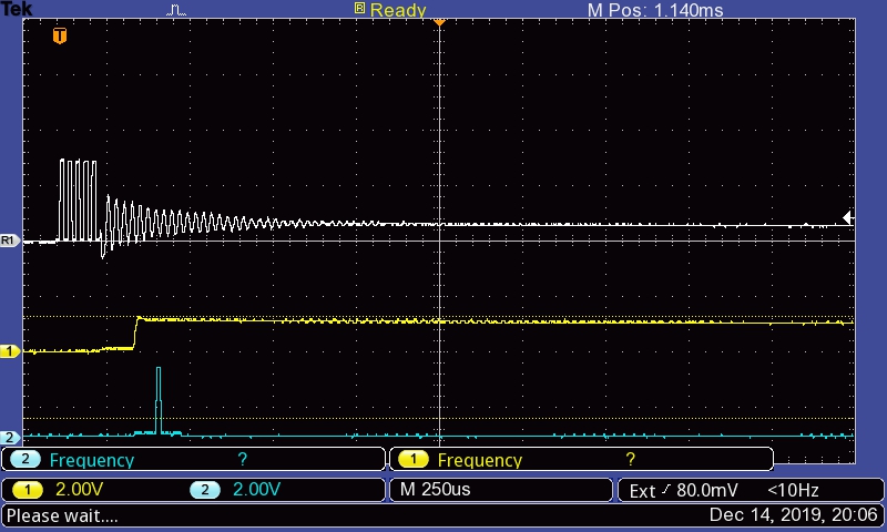
In my setup of the TDC1000 which is as in the schematic below, the received signal strength is very low! My transducers are 400ST (for transmit) and MA40S4R (receive) and both are centered at 40kHz. My intended applications are distance and thickness measurements. For the setup below, I just tried to measure the distance to an object about 10cm in line-of-sight away from the setup. 

The gray is the TX, yellow is the RX and the blue is the STOP signal

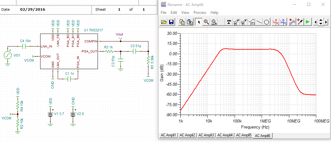
I simulated my filter as the first point of suspect, on TINA-TI and below is my setup and results

The transfer curve looks okay at 40kHz. What could be going wrong here?

Thanks,

Tushar

  • I guess the pictures don't show on my original post. So here they are:

  • Hi Tushar,

    I'd like to make an initial comment that the PGA460 or TUSS4470 are better devices to choose for low frequency (40kHz) operation of the Murata MA40S4R/S transducer pair. The main disadvantage when using the TDC1000 for air coupled low frequency operation is that it only offers a maximum of 21dB of analog front end gain. This is typically not sufficient for these types of use cases. The PGA460 and TUSS4470 both offer up to 90dB of AFE gain, which enables a greater dynamic range. The TDC1000 should only be considered for applications when using liquid coupled high frequency (0.6-4MHz) transducers in level sensing and concentration measurements. Also, the TDC1000 can only create a drive voltage of 5Vpp, whereas the PGA460 and TUSS4470 can drive with much higher voltages (upwards of 300Vpp where required).

    If you are to continue using the TDC1000, consider the following:

    • Because your transmitter is at TX1, and your receiver is at RX2, you should be using TOF_MEAS_MODE=0 and CH_SEL=0.
    • Maximize your record length by setting TIMING_REG to 0xFF. This enables a max record length of ~2m in air.
    • Your BPF network still has the 40kHz frequency out of band, which may be another reason why your signal is weak. Try to center the BPF such that the peak/plateau is at 40kHz with a gain of ~20dB. This plateau currently sits at 2MHz with your external values.

    Once again, I strongly encourage you to use a different device. You can compare the various ultrasonic IC on the ultrasonic E2E FAQ here: https://e2e.ti.com/support/sensors/f/1023/t/748143

  • Hi Akeem

    Thanks for your suggestions!

    Can I get a higher closed loop gain from the LNA by reducing the value of the external resistor Rin, since I read that the LNA has a 50MHz GBW? This would give me the added benefit of attenuating unwanted higher frequency noise.

    Thanks

    Tushar

  • Hey,

    I just found out that I had a Cin connected - the default setting - instead of an Rin in the simulation. But the LNA_FB pin, by default, was connected to VDD. As per datasheet, if LNA_FB is HIGH, we have a RESISTIVE feedback.

    Nevertheless, I went ahead and connected an Rin of 900ohm and did the sim and I get the transfer curve below.

    I wasn't expecting a curve like that.

    So, I thought maybe the LNA_FB logic is reversed here and connected it to GND. But there was no change at all in the transfer curve. 

    But I still don't understand the curve. Per my calculations, the value of the passives that I have chosen should produce a band pass effect with rollover frequencies at approximately 6kHz and 100kHz. 

    Below is my setup in simulation. Can you help me understand if I am doing something wrong?

    Thanks,

    Tushar

  • Hi Tushar,

    I am not certain how well the simulation handles a series-resistive input, but by increasing the series-capacitive input to 10nF, and maintaining the default components everywhere else for the BPF, the in-band gain of 10 results in a bandpass response between 30 kHz and 5 MHz. This should enable 40kHz signal detection on the board. Let's see how well this works for you before modifying the other external components.

  • Hi Akeem, so we can say that the series input capacitance, Cin, has no effect on the in-band gain? It was 10 earlier as well.

    Regards,

    Tushar

  • Tushar,

    Correct, the series input capacitance appears to primarily shift the band pass frequency response. Some preliminary testing with the other passives may slightly increase the in-band gain, but you should use an external gain stage with the BPF between the PGA_OUT and COMP_IN pins to add additional gain.

  • Got it. 

    I will try the setup recommended by you. 

    I checked out the documentation of the alternative parts recommended by you but I see that those are powered by voltages greater than 5V whereas I am limited by voltage to 3V. Are there any other parts that meet this voltage range?

    Thanks

    Tushar

  • Hi Tushar,

    The TUSS4470 and TUSS4440 have a VDD supply requirement of 3.1-5.5V, so these would be your best low voltage options if your only available supply rail is ~3V. Since you are not using a voltage boost or step-up anywhere, you should consider using the TUSS4440 to leverage the transformer driver. The transformer driver will can convert the DC 3V supply up to 60Vpp at the secondary since most transformer drivers use a 1:1:10 center-tap turns ratio. You can control the excitation voltage by adjusting the TUSS4440's driver current limit between 50-500mA. The transformer driver will ensure you generate the maximum amount of sound pressure level during the echo transmit phase to maximize your detection range.