This thread has been locked.

If you have a related question, please click the "Ask a related question" button in the top right corner. The newly created question will be automatically linked to this question.

AWR1843: I want to configure this chirp in awr 1843

Part Number: AWR1843
Other Parts Discussed in Thread: AWR1243, DCA1000EVM

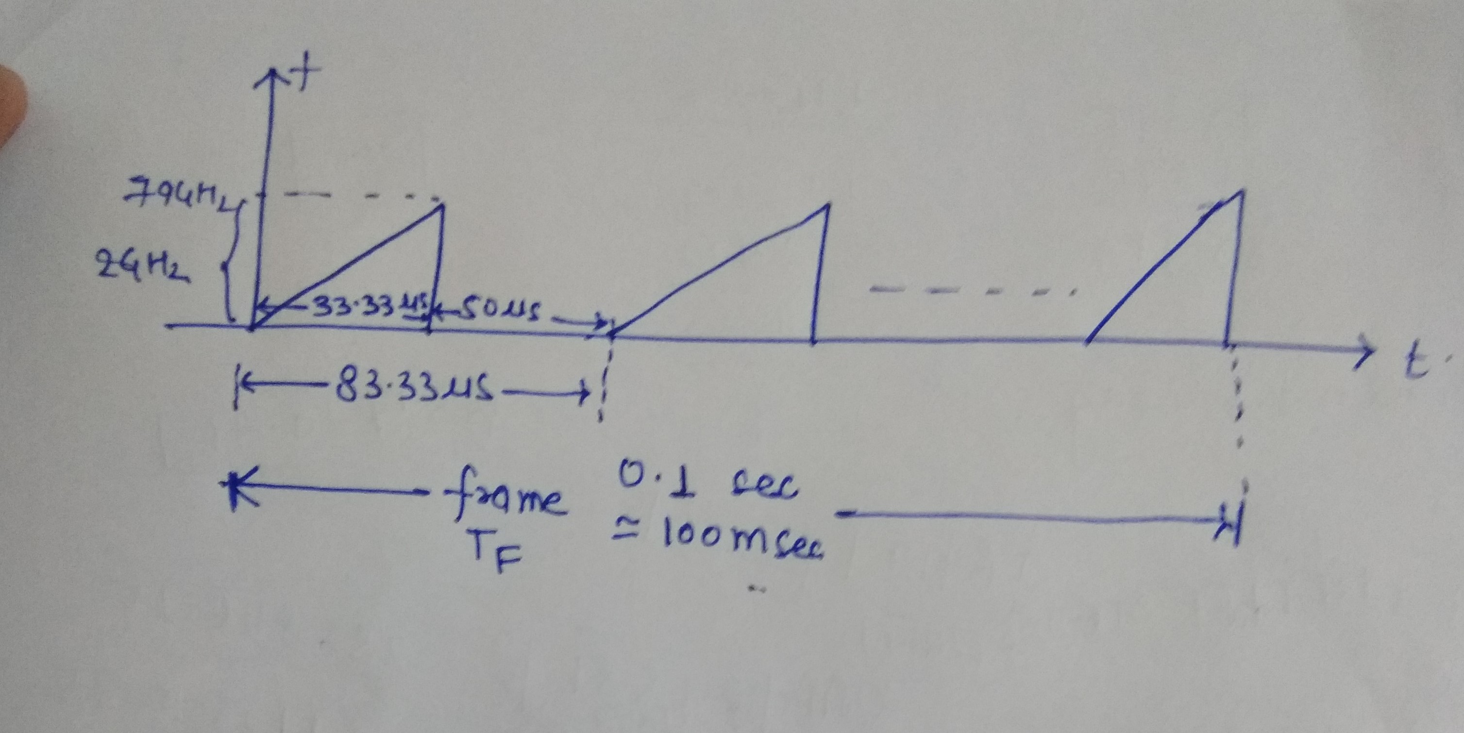
I want to configure the above chirp in using awr1843, I have the following confusion please help me, Note: Ramp slope =60 Hz/sec  (is missing in figure)

1. for calculating the  chirp duration in the mmwave studio what should be the ramp start and ramp end time, (should it be 83.33 microseconds or 33.33 microseconds) 

2. What should I select the ADC to start sampling , Is it equal to the chirp on time i.e 33 microseconds.  

3. If the 2nd case is correct then how to make the ramp duty cycle less than 50 %, and if the first case is correct then how to make the ramp bandwidth 2GHz( I have selected the slope 60e12 Hz/sec)

Please tell me the values of the parameter to be taken so that I can configure the same chirp.

Thank you

  • Hi,

    Have you tried to use the Ramp Calculator in mmwave studio?

    Thank you

    Cesar

  • hi Cesar Thanks for the reply

    Yes, I have tried to use the Ramp Calculator, I wonder that in ramp calculated there is an option to calculate the duty cycle and other things that I am asking in my question.

    I have also read all the related documents and threads (like the ramp programming pdf swra553a etc). In the ramp calculator, the calculation is for the duty cycle 100% I guess.

    Please answer my questions 1,2 and 3 accordingly.

    regards

    Neeraj

  • Dear Cesar,

    I have confusion in selecting a few parameters value as my chirp on time is 33.33 microseconds and total chirp time is 83.33 microseconds, from which it is obvious that the duty cycle of the chirp is less than 50%. I have taken slope (S) 60e12 (Hz/sec) to get the required bandwidth of 2GHz in 33.33 microseconds. Now for the 1843 device when I want to generate the same chirp then the ramp start and ADC start time are let's say 10 microseconds and then what should be the ADC and ramp stop time? Should the ADC stop time is equal to chirp on time i.e 33.33 microseconds and ramp stop time is 83.33 microseconds. In that case can you please explain to me the analogy. Then in the end I need to add idle time?

    Note: I have read all the available documents (training videos, documents, etc) and the related threads to this but I could not finds a suitable answer for this query. So I request you please explain in details

    Regards

    Neeraj


  • Neeraj,

    So please correct me if I am wrong, you are looking to create a set of chirps with the following parameters:

    Start frequency: 77 GHz

    Slope: 60 MHz/us

    Ramp end time: 33.33333 us

    Total chirp bandwidth: 2 GHz

    Idle time: 50 us

    It also looks like you are trying to set your frame periodicity to 100 ms.

    You need to determine the following elements to complete your profile configuration:

    ADC start time

    ADC samples

    Sample rate

    Additionally, you need to determine how many chirps per frame you would like to have.

    Let's say you use the following inputs for these 4 variables:

    ADC start time: 1 us

    ADC samples: 256

    Sample rate: 8000 ksps

    Chirps per frame: 128

    With this configuration, you would have an overall duty cycle of 11.9% and a 4.3% active-ramp duty cycle.

    Since there are 128 chirps per frame, the total active chirping time (idle time + ramp end time) = 83.3333 us * 128 = 10.666 ms. Since your frame periodicity is 100 ms, you would have 89.333 ms of interframe time before the next frame begins.

    You can modify the 4 values that I mentioned earlier to fit your particular application. But your question of duty cycling is a ratio of the active chirping time to the frame periodicity. The active chirping time is the product of the number of chirps per frame with the sum of the idle time and ramp end time per chirp.

    You can set the ADC start time to work within the 33.333 us of the active chirp. You just need to set the sampling rate at a rate where you can achieve the desired number of ADC samples before the ramp end time.

    Regards,

    Kyle

  • Hi Kyle 

    Thank you so much for your reply. I got answer of most of the question, but few confusions are remaining please if you can answer them

     let's say I have selected the ADC sampling =5000 ksps.

    If I need a maximum distance of 100 m

    so from Dmax= Fs*c/2S, using I got the slope 7.5 MHz/microseconds.

    If the required bandwidth = 2GHz, so the ramp end time= 266.6 microseconds, lets idle time= 50 microseconds.

    Following are my queries

    1. Number of ADC sample =ramp end time/sampling time? i.e., 1330 samples. Is this correct way to calculate the number of ADC samples, and what is the limit of the maximum number of ADC samples?

    2. For the frame duration of 100 ms, the number of chirps required =frame duration/idle time + ramp end time?

    3. How to calculate interframe time?

    4. Inmmwave studio in the sensor configuration tab, in Frame and Chirp Tab, what will be the value of the different parameters, for example, start chirp T, end chirp TX, a number of chirps loop, periodicity, etc.

    Note: I want to capture the single transmitter and single receiver raw ADC data For which I need the chirp configuration, as, during the calculation, I got to know that with the 60 MHz/us slope rate, I will not get the 100 m maximum distance, so I have adjusted my slope accordingly.

  • Neeraj,

    The number of ADC samples is a function of how many range bins you want for each chirp. It is not a simple ramp end time/sampling time calculation. You would preferably like to choose an ADC sample number that is a power of 2 (64, 128, 256, etc.) as this will simply FFT calculations and avoid extra zero padding. The maximum number of ADC samples is set by the BSS firmware, found here:

    rlUInt16_t  numAdcSamples
      Number of ADC samples to capture in a chirp for each RX
    Valid range: 2 to MAX_NUM_SAMPLES
    Where MAX_NUM_SAMPLES is such that all the enabled RX channels' data fits
    into 16 kB memory memory in AWR1243/xWR1443 or 32 kB memory in xWR1642/
    xWR6843/xWR1843, with each sample consuming 2 bytes for real ADC output
    case and 4 bytes for complex 1x and complex 2x ADC output cases
    number of RX chains ADC format Maxinum Number of samples
    4 complex 1024
    4 Real 2048
    2 Complex 2048
    2 Real 4096

    However, please keep in mind that you are going to be limited in the shared L3 memory based on how many chirps per frame you choose.

    Similarly, the number of chirps required per frame is a function of how many Doppler bins you want per frame. It is also not a simple frame duration/(idle time + ramp end time) calculation. The number of chirps per frame determines how many velocity bins you have in a given frame.

    So in both cases, the number of ADC samples per chirp and number of chirps per frame are not simple formulas/calculations. They are determined by the use case of the device and often involve trade-offs between number of range bins, number of Doppler bins, range resolution, velocity resolution, etc.

    I would highly recommend that you review the mmWave Training series found here: https://training.ti.com/mmwave-training-series

    This will help expound on the topics discussed in this thread.

    Interframe is the time between the end of active chirping in one frame and the start of chirping in the next frame.

    As stated in my previous post: Since there are 128 chirps per frame, the total active chirping time (idle time + ramp end time) = 83.3333 us * 128 = 10.666 ms. Since your frame periodicity is 100 ms, you would have 89.333 ms of interframe time before the next frame begins. At 10.6666 ms, the 128 chirps have all completed and there are 89.3333 ms of time where the radar is not actively chirping. This time is needed for interframe processing (Doppler FFT, CFAR, AOA, additional algorithms).

    In your case, you are looking to use a single chirp as the basis for constructing your frame.

    You would set the profile values (start frequency, frequency slope, etc.) in the profile section. Then you would create one chirp (chirp 0) in the chirp section. You can have one, two, or three TX antennas enabled for this chirp. That is up to you, but for the purposes of this exercise, just enable one TX.

    Then in the frame section, both your start chirp and end chirp would be 0, since you only have one unique chirp. Then you would specify the number of chirp loops to 128 so you would have 128 chirps in the frame, all based on chirp 0. Then you would set the frame periodicity to 100 ms since that is the periodicity you noted in your initial post. And then you can set the number of frames to your desired number of frames. If you set this value to 0, the sensor will chirp indefinitely until you press the "Stop Frame" button in mmWave Studio.

    You will need a DCA1000EVM in order to capture the raw ADC data.

    Regards,
    Kyle

  • - Hi Kyle 

    Thanks a lot for your eloquent answer, I have DCA 1000 for the raw data capture.

    I have a good knowledge of radar parameters, like range resolution doppler resolution, and I have watched the whole training session.

    1. I have done a simulation of radar now, and I want to verify my results with experimental data, so I want to generate Chirp, which I used in the simulation.

    So accordingly, I don't want to compromise with the range resolution and doppler resolution. But in my simulation case, I have taken the slope 60 MHz/uS and sampling frequency 40MHz, but now with this device, the sampling frequency is 12.5 MHz, so for the same range resolution I need to change the slope and chirp duration, as sampling frequency also decides the maximum range (dmax=Sampling frequecy*C/2*slope); so from here

    I have fixed the slope for the Dmax=100 m, and sampling frequecy= 5000ksps, as slope=7.5 MHz/uS

    for the Bandwith =2GHz, Chirp on time( ADC on sampling on time)=266.6 uS,

    So from here, I got the ADC sample 1330.

    Is it not the correct way to approach? If not, so can you please suggest the right approach?

    2. From the capture ADC raw data from the single transmitter and single receiver, I want to do my processing, so for reading the .bin file to get the complex ADC data, is there any Matlab script is available for awr1843, or 1643 Matlab script will work for it with slight modification?

    3. For the ADC sample, is it compulsory to choose the in the form of 2^power ?or any number will work, (baring zero paddings and all) as the Matlab script for awr1643 is not working for the single receiver and the above-discussed case.

  • 4. For the of interframe time, I have small doubt that where I will use it during the chirp configuration, is it automatically taken care of according to the periodicity? Is there a minimum interframe time is required?

  • Neeraj,

    Your approach appears that it would work, assuming that you set the ADC start time to 0. Typically, the ADC start time is not set to 0, but you can certainly proceed with this approach.

    Just be aware that 1330 is a large number of ADC samples. Even in a 1 TX & 1 RX scenario and assuming you set the ADC in complex mode, a single chirp will have the following size:

    ADC Data = (2 bytes per part) * (2 parts) * (1330 samples per chirp) 

    ADC Data = 5.320 KB per chirp

    where the 2 parts represent the real and imaginary 16-bit data

    Now let's say you have 128 chirps per frame, you radar cube size would be over 680 KB, approaching 75% of the shared L3 memory. This does not leave much space for subsequent calculations. If you added just one additional RX antenna, the 1D FFT radar cube would not fit into the shared L3 memory because the number of ADC samples per chirp is so high.

    But again, this is a design decision that you have to make and weight against other factors. You ultimately have to make that decision.

    An example MATLAB script for parsing data captured with the DCA1000EVM is found in this folder location:

    C:\ti\mmwave_studio_02_01_01_00\mmWaveStudio\MatlabExamples\singlechip_raw_data_reader_example

    This is for the current release of mmWave Studio, found here: https://software-dl.ti.com/ra-processors/esd/MMWAVE-STUDIO/latest/index_FDS.html

    Again, for the number of ADC samples per chirp, please refer to my earlier post regarding the firmware limitations of numADCsamples.

    It is a recommendation to use a power of 2 to maximize the use of the FFT engines on the device.

    With regards to interframe time, it is recommended to keep the duty cycle time at or below 50%. This suggestion is driven primarily by thermal considerations.

    Regards,
    Kyle

  • Dear Kyle

    Thanks a lot for your answer 

    I had one last doubt 

    Can you please suggest to me that what can be the maximum number of chirp loop we can take (in mmwave studio there are only 255 chirp options available) but in the related document, I have read that we can take 512 chirps per frame. If I can take 512 chirps per frame then please tell me, how?

    In that case, if I want to increase the maximum velocity range (as we have a limited number of chirp per frame, maximum velocity=number of chirp per frame*Doppler resolution*wavelength*0.5, where Doppler resolution =1/frame time) so what are the possible option, If I don't want to change the maximum range and range resolution and doppler resolution.

    Thank you.

  • Neeraj,

    In a typical TDM MIMO case, you would create three different chirps, all based on the same profile. The chirps would be different because:

    1. Chirp 1 would only enable TX1
    2. Chirp 2 would only enable TX2
    3. Chirp 3 would only enable TX3

    Now when you go to configure the frame, you would specify the start chirp as chirp 1 and the end chirp as chirp 3. And then if you were to specify the number of chirp loops at 128, you would have a total of 3 * 128 = 384 total chirps per frame. Increasing the number of chirp loops would result in more total chirps per frame. 172 chirp loops, for example, would give you 516 chirps per frame based on the example above.

    You can create up to 512 unique chirp definitions and then have up to 256 chirp loops per frame. So based on this information, you can easily have 512 chirps per frame. But again, it all comes back to how many ADC samples per chirp are specified and if the resulting 1D FFT radar cube will fit into the shared L3 memory. There are always trade-offs when it comes to designing the chirps for your application.

    This leads to the final part of your last post. You will have to make design trade-offs if you want to increase the maximum velocity. Please refer to Table 1 in this white paper on programming chirp parameters to see how different considerations affect the chirp design. In most cases, having a larger maximum velocity comes at the cost of a decreased bandwidth in each chirp. A lower bandwidth, in turns, results in a decreased range resolution. You will have to make a decision based on your application on which chirp parameters have a higher priority.

    https://www.ti.com/lit/an/swra553a/swra553a.pdf

    Regards,
    Kyle