This thread has been locked.

If you have a related question, please click the "Ask a related question" button in the top right corner. The newly created question will be automatically linked to this question.

AWR1443BOOST: AOA estimation

Part Number: AWR1443BOOST
Other Parts Discussed in Thread: AWR1443, AWR1243,

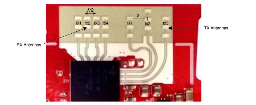
    According to some documents of TI, the receiving antennas of AWR1443 are arranged as follows. 

Fig. 1

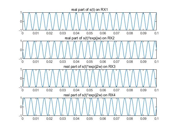
     If we assume the expression of the signal at RX1 is s(t), because the signal at other antenna is a delayed version of s(t), then the signal at RX2, RX3, RX4 can be expressed as s(t)*exp(-j*pi*sinθ), s(t)*exp(-j*2*pi*sinθ), s(t)*exp(-j*3*pi*sinθ) respectively. Then, an angle-FFT on these signals corresponding to different RX antennas will generate a peak at ω=-pi*sinθ, which means that the angle estimated by angle-FFT is negative. In other words, if the target is on the right of the arrays, the angle is negative.
    However, in our experiments, when the target is on the right of the antenna arrays, we can obtain a Range-Angle-Map as follows.
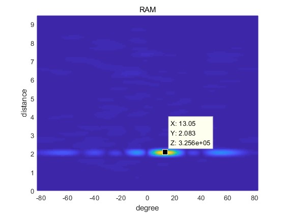
Fig. 2

     From the picture we can see that, when the target is on the right of radar, the angle estimated by angle-FFT is positive, but this result is contradictory to our analysis.
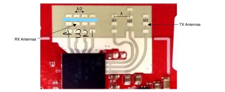
     However, if the receiving antennas were arranged as follows, the experiment result would be consistent with the analysis.
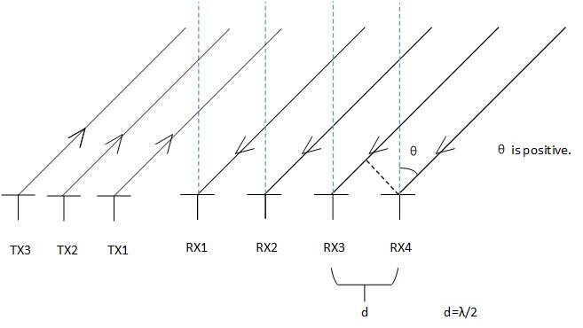
Fig. 3

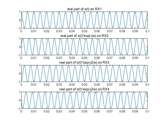
     In Fig.3, the signals received by RX1, RX2, RX3 and RX4 can be expressed as s(t), s(t)*exp(j*pi*sinθ), s(t)*exp(j*2*pi*sinθ), s(t)*exp(j*3*pi*sinθ) respectively. Then an angle-FFT on these signals will generate a peak at ω=pi*sinθ and this means that the angle estimated by angle-FFT is positive. What’s more, this analysis is consistent with our experiment result.
     So I think the antenna arrangement shown in Fig. 3 is correct and there may be some errors in some documents, but I’m not sure I’m right. So I want to know whether my analysis is correct, thank you.

  • Hello,

    The 2D FFT plot you are shared is showing the object to the right the radar , which is where the object really is. So your 2D FFT seems to be correct. Figure 3 is how the Rx array is on the EVM ,  RX1 is on the left and Rx4  is on the right.

    Regards,
    Vivek

  • Thanks for your reply. 

    The following figure was captured from AWR1443BOOST, AWR1243 EVM mmWave Sensing Solution User's Guide. 

    Fig. 4

    Do you mean this arrangement of receiving antennas shown in Fig. 4 is wrong and the actual arrangement of receiving antennas is as follows?

    Fig. 5

  • Hello,

    Apologize for the delay. The Fig 4 in the user guide is correct. Let me double check on the angle computation and get back.

    Regards,
    Vivek

  • HI, 

    In fig 1., The recieved signals on RX1, RX2, RX3 and RX4 be [s(t) s(t)*exp(j*pi*sinθ), s(t)*exp(j*2*pi*sinθ), s(t)*exp(j*3*pi*sinθ)]. This is because Rx2, Rx3, Rx4 have to travel an extra lambda/2. In other words, they are delayed (by pi*sin(theta)) versions of the signal at s(t). 


    Regards

    Anil

  • Hi, 

    Thanks for your reply. Of course, the received signal on RX2, RX3 and RX4 are delayed version of signal on RX1. Now we assume the target is on the right of radar, just as the fig.1 showing. If the delayed versions of s(t) can be expressed as s(t)*exp(j*pi*sinθ), s(t)*exp(j*2*pi*sinθ), s(t)*exp(j*3*pi*sinθ) respectively, where s(t)=exp(i*2*pi*200*t), then we can plot these signals using matlab. The following picture shows the result. 

    Fig. 6

    So we can see that, the signal on RX2, RX3 or RX4 is not a delayed version of s(t). In fig. 1, if the target is on the right of radar, I think the signal at RX2, RX3 and RX4 shhould be expressed as s(t)*exp(-j*pi*sinθ), s(t)*exp(-j*2*pi*sinθ), s(t)*exp(-j*3*pi*sinθ). The following picture shows these signals. 

    Fig. 7

    This picture seem more resonable. The signal on RX2, RX3 or RX4 is a delayed version of s(t). So could you tell me if my thought is correct?

    Thank you. 

  • Hi, 

    I didn't understand your post -- Could you explain further? It is difficult to look at two sinusoids and say one is a delayed version of the other (since they repeat every period).

    Regards

    Anil   

  • Hi,

    Thanks for your reply. According to The fundamentals of millimeter wave.pdf, unambiguous measurement of angle requires |ω| < 180°, where ω is the phase difference between two consecutive antennas. Thus, the phase difference between two consecutive signals in Fig. 7 should be lower than pi. Thus, the signal on RX2, RX3 or RX4 shown in FIg. 7 is a delayed version of that on RX1. 

    So in my opnion, in Fig. 1, the received signals on RX1, RX2, RX3 and RX4 should be s(t), s(t)*exp(-j*pi*sinθ), s(t)*exp(-j*2*pi*sinθ), s(t)*exp(-j*3*pi*sinθ). If my conclusion is wrong, please let me know in time. 

    Thanks. 

  • HI, 

    As I explained earlier, the recieved signals on RX1, RX2, RX3 and RX4 are [s(t) s(t)*exp(j*pi*sinθ), s(t)*exp(j*2*pi*sinθ), s(t)*exp(j*3*pi*sinθ)].

    This is because Rx2, Rx3, Rx4 have to travel an extra lambda/2.  


    Regards

    Anil