This thread has been locked.

If you have a related question, please click the "Ask a related question" button in the top right corner. The newly created question will be automatically linked to this question.

IWR6843ISK: How to get the antenna pattern - Continue.

Part Number: IWR6843ISK
Other Parts Discussed in Thread: MMWAVEICBOOST, , IWR6843

Hi TI team,

 Base on the previous post, https://e2e.ti.com/support/sensors/f/1023/p/905101/3346053, we know how the antenna pattern is measured from swru546c.pdf (the document of "MMWAVEICBOOST and Antenna Module User's Guide (Rev. C)").

 Would you provide more detail about how the radiation pattern of the on-board antenna is being measured?

 Take the IWR6843ISK in the user guide as example, different combinations of the pattern are shown in figure 80, 81.
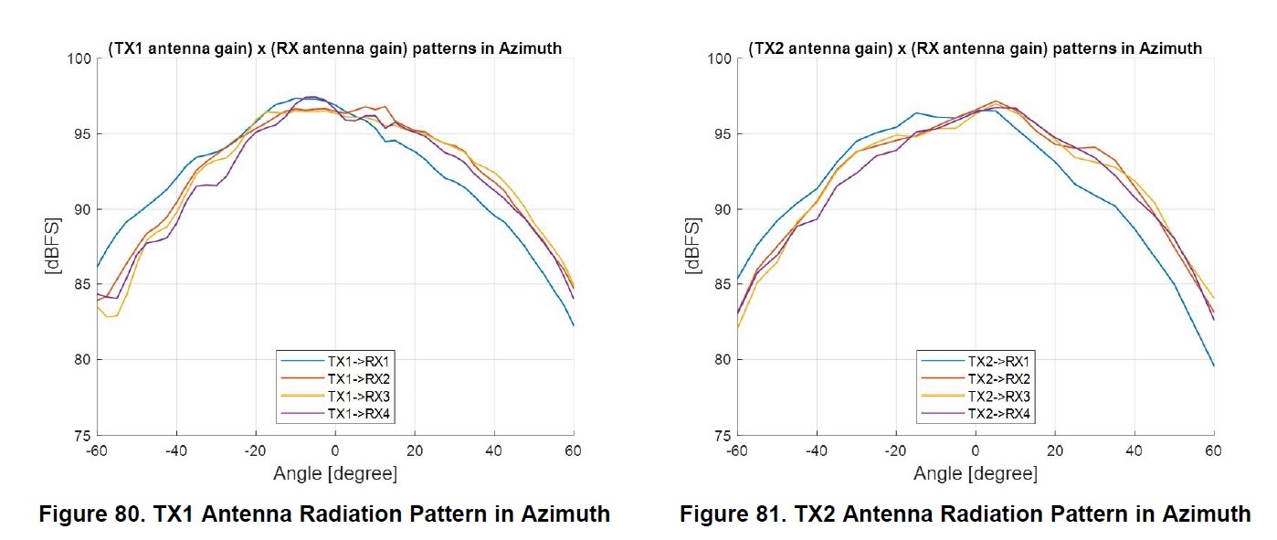
 1). How to control desired TX and desired RX since there are 3TX and 4RX? I assume it is done by the mmWave_Demo_Visualizer, right?

 2). Is it necessary to fix frequency when measuring the radiation pattern? Most of antenna lab needs CW in order to get the pattern, but IWR6843 is FMCW radar, can mmWave_Demo_Visualizer supports CW mode?

 It will be nice if you can provide more insight about the process of this measurement. We would like to measure our antenna performance on our board.

Thank you.

  • HI, Jesse:

    To measure the antenna radiation pattern, we capture raw ADC data, which is not available through out of box demo or mmWave_Demo_Visualizer.

    The lab set up:  we use the Anechoic Chamber and a corner reflector.  The sensor is mounted in a motorized rotator.  The automation script will capture raw data of different rotation angle.  FMCW signal will be sent, reflected back and go through the RX chain.  Different FMCW chirp configuration will result in slightly different radiation pattern because the gain is related to the frequency.    

    The post processing: 2D FFT (range and Doppler FFT) is used to post processing the raw ADC data.  The power of (range, Doppler) bin, that represent the target, is recorded for every antenna pair to plot this gain curve.  The value of this power is related to the TX power, TX antenna gain, RX antenna gain, propagation loss, RCS, processing gain, and scale change, which is hard to interpolate.  Therefore, we only use the relative value in this figure to understand the radiation pattern, i.e., the gain change over the rotation angle.  In addition, this gain represent the combination of TX antenna gain and RX antenna gain. 

    So to answer your question,

    1) mmWave_Demo_Visualizer is not used for this measurement, and we configure a TDM-MIMO chirp to measure all 12 visual antenna pair together.  

    2) Sending CW curve is not supported by SDK out-of-box demo, but you can use radar studio to send CW curve.    Sending and receive CW curve within the sensor will loss the target information.   I know the characterization team use CW curve to measure the TX gain for different frequency.  But they are using a horn antenna and spectrum analyzer on the other side to achieve that.  

    Best,

    Zigang

  • Hi Zigang,

     Thanks for that useful info.

     So the mmWave Studio radio tool, " https://www.ti.com/tool/MMWAVE-STUDIO " will need to use DCA1000 for capturing raw ADC data, which seems a more complex way.

     Could I use the mmWave_Demo_Visualizer by setting the parameter of "channelcfg" to select specific TX, and RX antenna, and design a proper chirp with very small slope and longer time to get a similar result?

     I mean, if I can select a specific TX by the proper setting of channelCfg and chirpCfg, and measure the range FFT plot for signal related power to get the similar picture of antenna patter.

     For example, below is setting for 1T4R on IWR6843,

       channelCfg 15 1 0

       chirpCfg 0 0 0 0 0 0 0 1

     And, can I change it to below, which selecting another TX antenna for the measurement?

       channelCfg 15 4 0

       chirpCfg 0 0 0 0 0 0 0 4


  • HI, Jesse:

    If you use visualizer to get the range profile, all the signal on different RX chain are already coherently combined.  So you will not be able to get gain for separate TX-RX pair.   

    You can try enable only one TX and only one RX every time through channelCfg and chirpCfg..  

    Best,

    Zigang

  • Hi Zigang,

     Thanks, and will have a try.