This thread has been locked.

If you have a related question, please click the "Ask a related question" button in the top right corner. The newly created question will be automatically linked to this question.

AWR1642BOOST: mmWave Studio BPM MIMO Configuration

Part Number: AWR1642BOOST
Other Parts Discussed in Thread: DCA1000EVM,

Hi,

I have been trying to configure my AWR1642boost+DCA1000evm setup to BPM MIMO mode to obtain 2TX & 4RX (a virtual array of 8 receivers) and therefore a better angular resolution. So far, I was able to use my setup with 1TX with no problem but having some issues to understand the 2TX (BPM) mode configuration. I have read TI's MIMO Radar document , SDK document and bunch of threads. Eventually, these are the steps of how I configure mmWave Studio parameters for raw ADC data acquisition in BPM mode: 

1. Connection setup.

2. Under SensorConfig Tab, in Profile section choose a profile ID (I believe single profile ID is enough for BPM mode and it can be used by different chirps) and set parameters.

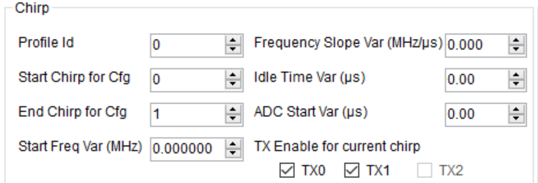
3. In Chirp section, create 2 chirps. First one is: Profile ID=0, Start Chirp=0, End Chirp=0, both TX0 and TX1 are checked (for simultaneous chirp sending) and Set; Second chirp is: Profile ID=0, Start Chirp=1, End Chirp=1, both TX0 and TX1 are checked again and Set.

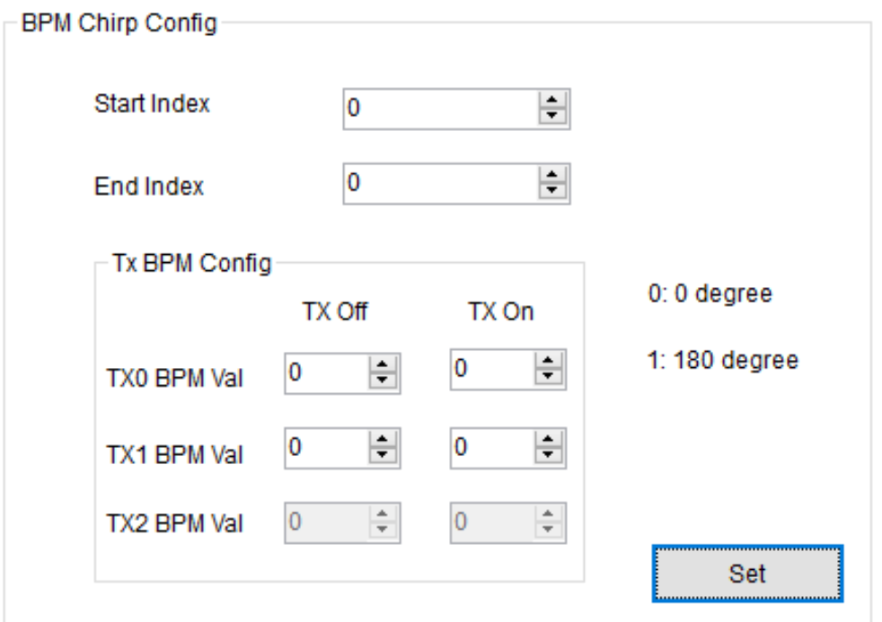
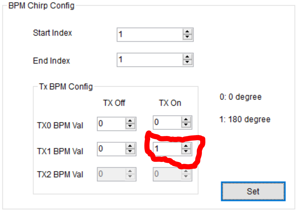
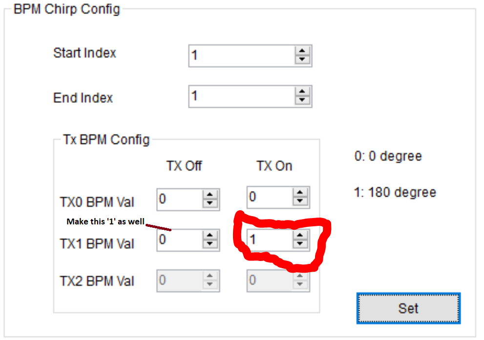
4. Go into BPMConfig tab. Go into BPM Chirp Config section. For the first chirp (in the MIMO Radar document (Section 4.2) it is referred as S_a=S1+S2): Start index=0, End index=0, TX0 BPM Val (TX On)=0, TX1 BPM Val (TX On)=0 and Set. For the second chirp (in the MIMO Radar document it is referred as S_b=S1-S2): Start index=1, End index=1, TX0 BPM Val (TX On)=0, TX1 BPM Val (TX On)=1 and Set. 

5. Under Sensor Config tab go into Frame section. Set Start Chirp TX=0, End Chirp TX=1 and other parameters.

6. DCA arm +Trigger frame to collect data.

So, my questions are as follows:

I) Is there anything wrong with this configuration or is it the right way of configuring BPM MIMO parameters? 

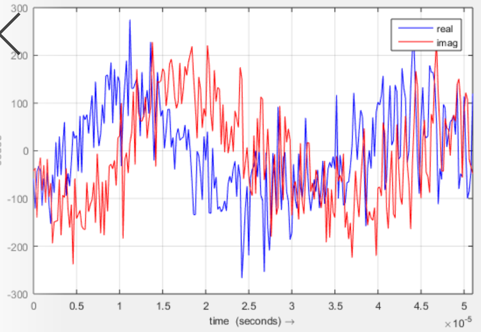
II) In raw data processing, according to the mimo radar document, we obtain s1 by averaging consecutive chirps ((S_a+S_b)/2) and s2 by ((S_a - S_b)/2). In this case, from 2 consecutive chirps (S_a and S_b) we get one s1 and one s2 but we should obtain two chirps from each of them according to the figure I believe, because simultaneous chirp transmission is the main advantage of BPM. So how do we obtain a total of 4 chirps out of S_a and S_b? Should we repeat s1 and s2 after obtaining them? This is what I do right now, I am replicating the chirps (s1 and s2) after obtaining them.

III) Do we need to do any further phase correction on chirps since we have sent S_b with 180 degree phase difference? If so, in which step? I guess it is recommended to do it after 2D-FFT (range-velocity/doppler map) but I am not really sure if it is a must because I can obtain micro-Doppler spectrograms without any phase correction. If it is a must for angle estimation, then it would be great to have some documents or guide to see how it is done. 

IV) How should i reshape my data after obtaining my radar data cubes for 2 TXs to get 8 channel data cube (ADC samples, # of chirps, # of RXs)? Can I just concatenate data cubes two TXs? If so, in which order like concat(TX0,TX1) or concat(TX1,TX0)?

Thanks in advance for your help!

Best,

Emre

  • Hello Emre,

    I would suggest you follow this relevant thread on BPM.

    https://e2e.ti.com/support/sensors/f/1023/p/909604/3361780#3361780


    Regards,

    Jitendra

  • Thank you for the information. I followed the steps you mentioned and got the following chirps for 1 transmitter case (Tx0):

    chirp 0:                                                                                                      


    chirp 1:


    But I am not sure why we are supposed to use only one TX. Isn't the advantage of using BPM simultaneous transmission from multiple transmitters as stated in the Mimo Radar document (see, section 4.2)?

    When i try to extend this to 2 antennas case, I enable both antennas in both chirp configurations and under BPM config tab I set chirp configurations as follows:

    Chirp Config:

    chirp 0 config:                                                                                                                                         


    chirp 1 config:


    According to the documentation, this is what I understand from Figure 10. (see '1's in the plot corresponds to 0 phase which is 0 in mmwave studio, and '-1's in the figure correspond to 180 degree which is 1 in mmwave studio). When I do this configuration like this, I get my chirps as follows:

    chirp 0:                                                                                                                   


    chirp 1:


    As you can see, there is no 180 degree difference but when I add phase to both antennas then I can get the 180 degree phase difference:

    chirp 1 config:                                                                                                         


    chirp 1: 


    As we can see this time we obtained 180 degree phase difference. So, doesn't this contradict with what document says? Because according to the document we should add phase only to one antenna. Please correct me if I am wrong.

    Also if you have any information or a thread you know about my II. and III. questions, it would be great! 

    Best,

    Emre

  • Hello Emre,

    Other thread link I have mentioned was to demostrate the phase shift by 180 degree in the chirp plot.

    But in the real case you need to use two Tx (one with 0 deg and other with 180 deg)  to use the BPM feature of the device.

    And in the mmwave studio:

    You need to set value '1' for Tx off and on both together to enable 180 deg for specific Tx antenna.

    Regards,

    Jitendra

  • Thank  you for the clarification Jitendra. Please let me know if I am processing the raw BPM data in the right way. 

    Best,

    Emre