This thread has been locked.

If you have a related question, please click the "Ask a related question" button in the top right corner. The newly created question will be automatically linked to this question.

PGA460: PGA460 Issue in performace and deadzone while using 200khz trasnducer

Part Number: PGA460
Other Parts Discussed in Thread: MSP-EXP430F5529LP,

Hi,

I am developing 200khZ solution based on pga460 I am having few problems which i would like to disucess.

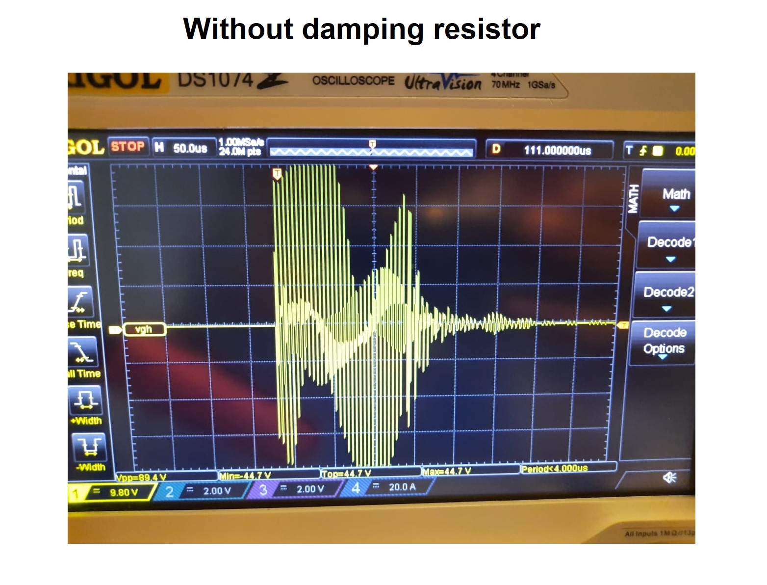
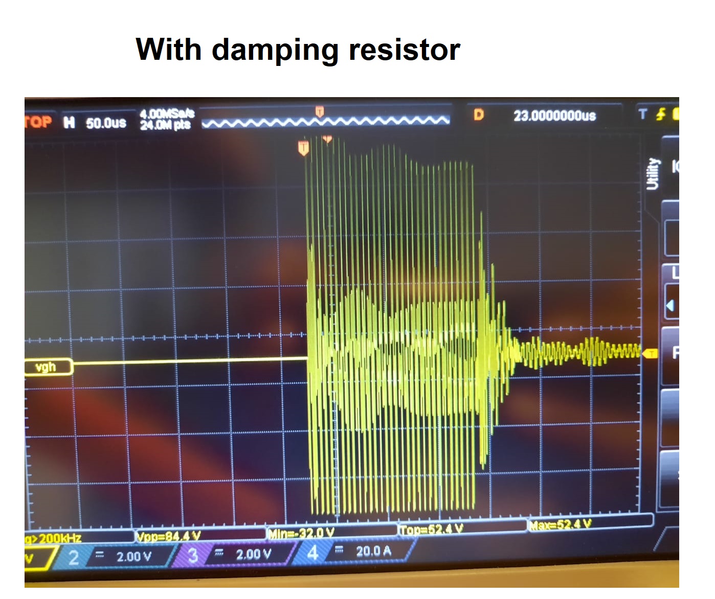
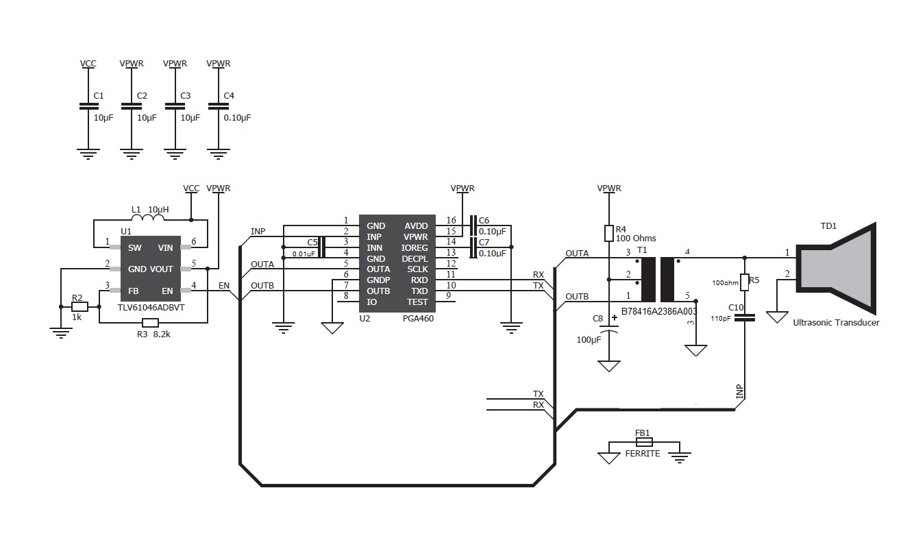
I am following reference design and no passives are place in paralelle to transducer. The following components are used in the design.

TLV61064A (Supply @ 7.5V)

Wurth Transformer 750317161

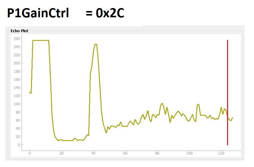
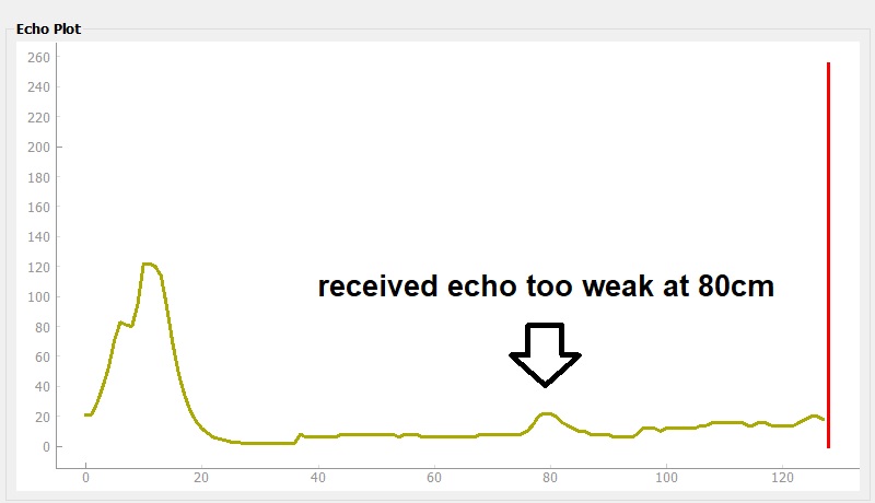
I am using echo profiling to finely tunned the system. From profiling data, it seems like the transducer is not generating strong echo, and therefore the intensity of the received echo is also very low. To tackle that problem I have increased P1GainCtrl to maximum 0x2C and it starts to work but now the deadzone is large around 14cm. I am also not satisfied with the performance overall sometimes it didn't detect the object at all.
I also tried epcos B78416A2386A003  but the same results. I have also noticed one problem that sensor only worked by turning off current limit feature CurrentLimP1 = 0xFF.
Please have a look at register settings. if there is any problem in settings.

Thanks

constexpr std::uint8_t TvGain0       = 0x44; 
constexpr std::uint8_t TvGain1 = 0x44;
constexpr std::uint8_t TvGain2 = 0x44;
constexpr std::uint8_t TvGain3 = 0x08;
constexpr std::uint8_t TvGain4 = 0x64;
constexpr std::uint8_t TvGain5 = 0x9A;
constexpr std::uint8_t TvGain6 = 0x99;

constexpr std::uint8_t InitGain = 0xC0;
constexpr std::uint8_t Freq = 0x11;
constexpr std::uint8_t DeadTime = 0x40;
constexpr std::uint8_t PulseP1 = 0x1F;
constexpr std::uint8_t PulseP2 = 0x10;
constexpr std::uint8_t CurrentLimP1 = 0xFF;
constexpr std::uint8_t CurrentLimP2 = 0xFF;
constexpr std::uint8_t RecLength = 0x11;
constexpr std::uint8_t FreqDiag = 0x63;
constexpr std::uint8_t SatFDiagTh = 0xEE;
constexpr std::uint8_t FVoltDec = 0x7C;
constexpr std::uint8_t DecplTemp = 0x0F;
constexpr std::uint8_t DSPScale = 0x00;
constexpr std::uint8_t TempTrim = 0x00;
constexpr std::uint8_t P1GainCtrl = 0x2C;
constexpr std::uint8_t P2GainCtrl = 0x2B;

constexpr std::uint8_t BPF_A2_MSB = 0xDD; // reg addr 0x41
constexpr std::uint8_t BPF_A2_LSB = 0xBA; // reg addr 0x42
constexpr std::uint8_t BPF_A3_MSB = 0xF3; // reg addr 0x43
constexpr std::uint8_t BPF_A3_LSB = 0x72; // reg addr 0x44
constexpr std::uint8_t BPF_B1_MSB = 0x06; // reg addr 0x45
constexpr std::uint8_t BPF_B1_LSB = 0x47; // reg addr 0x46
constexpr std::uint8_t LPF_A2_MSB = 0x7C; // reg addr 0x47
constexpr std::uint8_t LPF_A2_LSB = 0xD3; // reg addr 0x48
constexpr std::uint8_t LPF_B1_MSB = 0x01; // reg addr 0x49
constexpr std::uint8_t LPF_B1_LSB = 0x97; // reg addr 0x4A


constexpr std::uint8_t P1Thr0 = 0x88; // reg addr 0x5F
constexpr std::uint8_t P1Thr1 = 0x88; // reg addr 0x60
constexpr std::uint8_t P1Thr2 = 0x88; // reg addr 0x61
constexpr std::uint8_t P1Thr3 = 0x88; // reg addr 0x62
constexpr std::uint8_t P1Thr4 = 0x88; // reg addr 0x63
constexpr std::uint8_t P1Thr5 = 0x88; // reg addr 0x64
constexpr std::uint8_t P1Thr6 = 0x84; // reg addr 0x65
constexpr std::uint8_t P1Thr7 = 0x21; // reg addr 0x66
constexpr std::uint8_t P1Thr8 = 0x08; // reg addr 0x67
constexpr std::uint8_t P1Thr9 = 0x42; // reg addr 0x68
constexpr std::uint8_t P1Thr10 = 0x10; // reg addr 0x69
constexpr std::uint8_t P1Thr11 = 0x80; // reg addr 0x6A
constexpr std::uint8_t P1Thr12 = 0x80; // reg addr 0x6B
constexpr std::uint8_t P1Thr13 = 0x80; // reg addr 0x6C
constexpr std::uint8_t P1Thr14 = 0x80; // reg addr 0x6D
constexpr std::uint8_t P1Thr15 = 0x00; // reg addr 0x6E

 200kHz DM200.pdf

  • Hi Samuel,

    I am surprised you were able to get working results when pairing the 200kHz transducer with the WE 750317161 transformer, because this transformer is intended to be paired with low frequency (30-80kHz) transducers due to its 3mH inductance. The EPCOS B78416A2386A003 should generate a more efficient transmit pulse because it is intended to be paired with high-frequency (180-480kHz) transducers due to its lower inductance of 230uH.

    To debug:

    1. Can you oscilloscope probe the transducer's positive terminal to check and compare the transmit pulse integrity of the two transformer options.
    2. You should not need to disable the current limit to generate sufficient SPL. Typically, 200~300mA is sufficient. In fact, disabling the current is not recommended since this could damage the driver block if you don't externally limit the current.
    3. The FOV of the 200kHz is very narrow, so alignment to the target is crucial to enable proper detection. What is the targeted object?
    4. A digital of x16 or x32 is not recommended to for the burst decay stage. You should start with a low DG initially (x1-x4) for the short range, then bump up to a long range multiplier (>=x8) for the long range. You'll want to bring in your TH9 point much sooner to enable the LR multiplier immediately after decay. You'll have to use very short TH1-8 threshold time values to do so. You are currently using mid-code values (0x88), which are too long.
    5. Assuming you are using a UART connection, do you have the EVM's MSP-EXP430F5529LP board to connect to your PGA460, and use the GUI to check, compare, and optimize performance?
    6. You may need to add a damping resistor of 10kOhm (ideal starting value) in parallel to the transducer to reduce the decay/deadzone time. You can read more about the the matching components (parallel tuning capacitor and damping resistor) as described in section "3.4 Passive Tuning" of the PGA460 Ultrasonic Module Hardware and Software Optimization app report.

  • Hi Akeem,
    Sorry, that was a typo with the transformer model number I was testing it with the 750316928.
    1- Yes FOV of the 200khz is too narrow and I am trying to detect wall which should not be any problem.
    2- I have updated my gain (x4 for burst decay stage and x16 for long-range) , thresholds, and current limit setting. I have also added 10k damping resistor but still, I am getting more than 15cm deadzone. The incoming
    echo amplitude is too small so it is sometimes missing the object.
    3- I have recorded the echo burst stage on the oscilloscope and have attached the images in the message. From oscilloscope i have figured out the Vpp are very low. I couldn't figure out what is the issue.
    The attached images are recorded with B78416A2386A003 transformer operated at 7.5 so Vpp should be (7.5 x9 ) x 2 = 135V but oscilloscope has recoded Vpp 84V .
    I have also attached schematic can you check if we are doing something wrong.
    4- I do not have EVM board but I have written some script in python for echo plotting and I am sharing the plot as well.
    Thanks for your time.

    constexpr std::uint8_t TvGain0 = 0x8D; // reg addr 0x14
    constexpr std::uint8_t TvGain1 = 0xEE; // reg addr 0x15
    constexpr std::uint8_t TvGain2 = 0xEF; // reg addr 0x16
    constexpr std::uint8_t TvGain3 = 0x10; // reg addr 0x17
    constexpr std::uint8_t TvGain4 = 0xA5; // reg addr 0x18
    constexpr std::uint8_t TvGain5 = 0x20; // reg addr 0x19
    constexpr std::uint8_t TvGain6 = 0xC1; // reg addr 0x1A

    constexpr std::uint8_t InitGain = 0xC0; // reg addr 0x1B
    constexpr std::uint8_t Freq = 0x11; // reg addr 0x1C
    constexpr std::uint8_t DeadTime = 0x40; // reg addr 0x1D
    constexpr std::uint8_t PulseP1 = 0x1F; // reg addr 0x1E
    constexpr std::uint8_t PulseP2 = 0x10; // reg addr 0x1F
    constexpr std::uint8_t CurrentLimP1 = 0x3F; // reg addr 0x20
    constexpr std::uint8_t CurrentLimP2 = 0x3F; // reg addr 0x21
    constexpr std::uint8_t RecLength = 0x11; // reg addr 0x22
    constexpr std::uint8_t FreqDiag = 0x63; // reg addr 0x23
    constexpr std::uint8_t SatFDiagTh = 0xEE; // reg addr 0x24
    constexpr std::uint8_t FVoltDec = 0x7C; // reg addr 0x25
    constexpr std::uint8_t DecplTemp = 0x0F; // reg addr 0x26
    constexpr std::uint8_t DSPScale = 0x00; // reg addr 0x27
    constexpr std::uint8_t TempTrim = 0x00; // reg addr 0x28
    constexpr std::uint8_t P1GainCtrl = 0x22; // reg addr 0x29
    constexpr std::uint8_t P2GainCtrl = 0x22; // reg addr 0x2A

    constexpr std::uint8_t BPF_A2_MSB = 0xDD; // reg addr 0x41
    constexpr std::uint8_t BPF_A2_LSB = 0xBA; // reg addr 0x42
    constexpr std::uint8_t BPF_A3_MSB = 0xF3; // reg addr 0x43
    constexpr std::uint8_t BPF_A3_LSB = 0x72; // reg addr 0x44
    constexpr std::uint8_t BPF_B1_MSB = 0x06; // reg addr 0x45
    constexpr std::uint8_t BPF_B1_LSB = 0x47; // reg addr 0x46
    constexpr std::uint8_t LPF_A2_MSB = 0x7C; // reg addr 0x47
    constexpr std::uint8_t LPF_A2_LSB = 0xD3; // reg addr 0x48
    constexpr std::uint8_t LPF_B1_MSB = 0x01; // reg addr 0x49
    constexpr std::uint8_t LPF_B1_LSB = 0x97; // reg addr 0x4A


  • Hi Samuel,

    I suspect the weak echo is due to your distorted transducer driver voltage, resulting in a lower transmitted sound pressure level. The driving voltage should more ideal sinusoidal with fewer transients and offset. You may need to add a tuning capacitor in parallel to the transducer instead of just the damping resistor to better match the transformer to the transducer. Please refer to section "3.4 Passive Tuning" in PGA460 Ultrasonic Module Hardware and Software Optimization app report. You will most likely need to spot check a few capacitor values in the 50-1000pF range. I typically use a capacitor bank to sweep several values as I monitor the oscilloscope output of the transducer driver voltage.

    Your schematic looks fine. You may want to replace FB1 with a 0Ohm short to see if this also makes a difference.

  • Thank you for your time.