This thread has been locked.

If you have a related question, please click the "Ask a related question" button in the top right corner. The newly created question will be automatically linked to this question.

xWR6843 & DCA1000EVM: DCA1000EVM configure IP with "Timeout Error! System disconnected"

Part Number: DCA1000EVM
Other Parts Discussed in Thread: IWR6843, IWR6843ISK, MMWAVEICBOOST,

1.
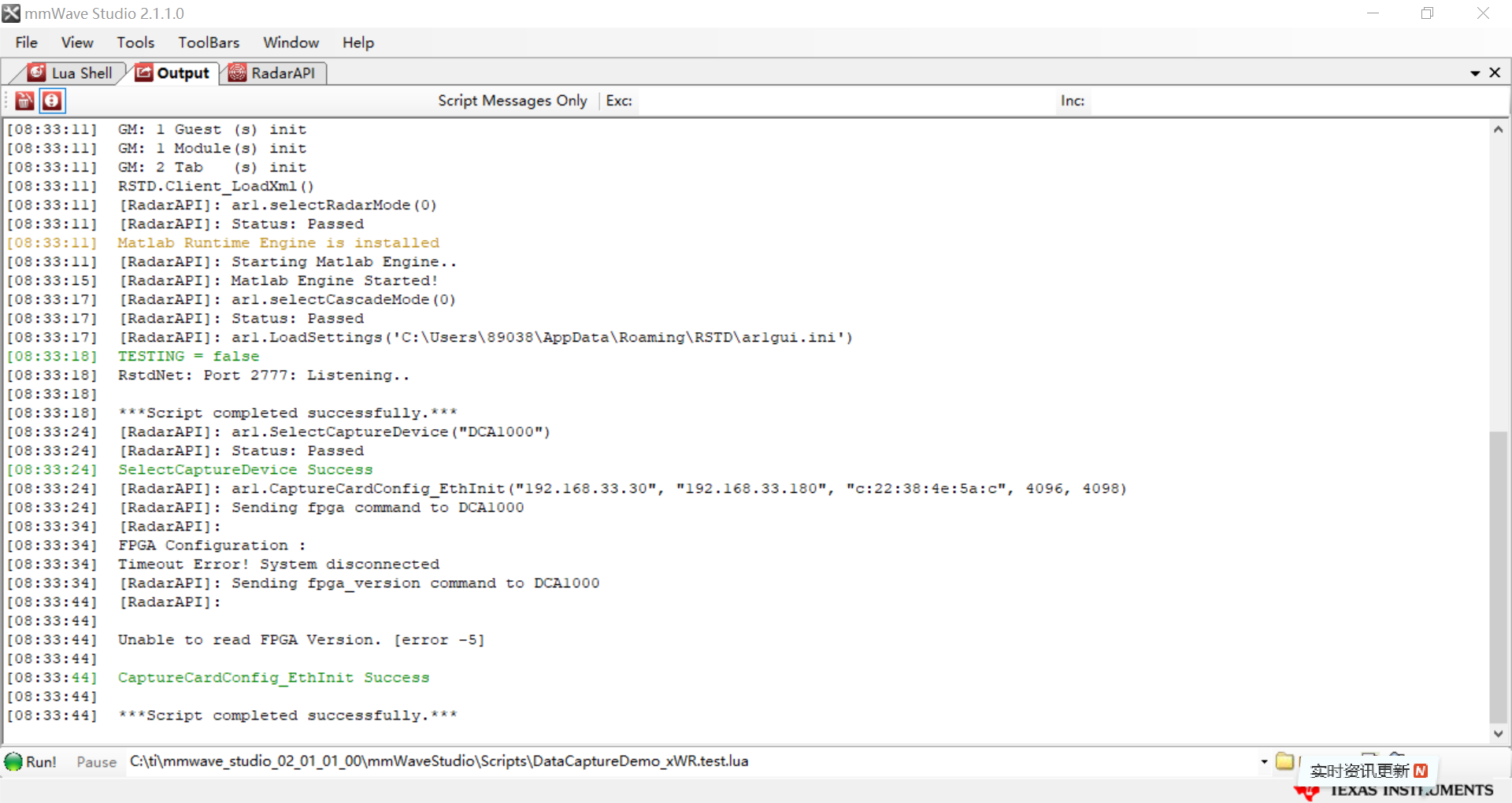
DCA1000 configure IP fail , what is the reason

1.1 as below:


[08:02:53] [RadarAPI]: ar1.SelectCaptureDevice("DCA1000")
[08:02:53] [RadarAPI]: Status: Passed
[08:02:53] SelectCaptureDevice Success
[08:02:53] [RadarAPI]: ar1.CaptureCardConfig_EthInit("192.168.33.30", "192.168.33.180", "c:22:38:4e:5a:c", 4096, 4098)
[08:02:53] [RadarAPI]: Sending fpga command to DCA1000
[08:03:03] [RadarAPI]:
[08:03:03] FPGA Configuration :
[08:03:03] Timeout Error! System disconnected
[08:03:03] [RadarAPI]: Sending fpga_version command to DCA1000
[08:03:13] [RadarAPI]:
[08:03:13]
[08:03:13] Unable to read FPGA Version. [error -5]
[08:03:13]


2.
2.1
There is a IWR6843 board(customer board) and DCA1000 board, I connect them with LVDS

2.2
IWR6843 board is burn software correct
It support output ADC info by LVDS, and need to test

2.3
IWR6843 support with 5V/3A power
DCA1000 is powerd by IWR6843 board

2.
DCA1000
FPGA_DONE_LED is green
5V_LED is green( it is indeed green,  cant now show obvious in snapshot picture)

2.5
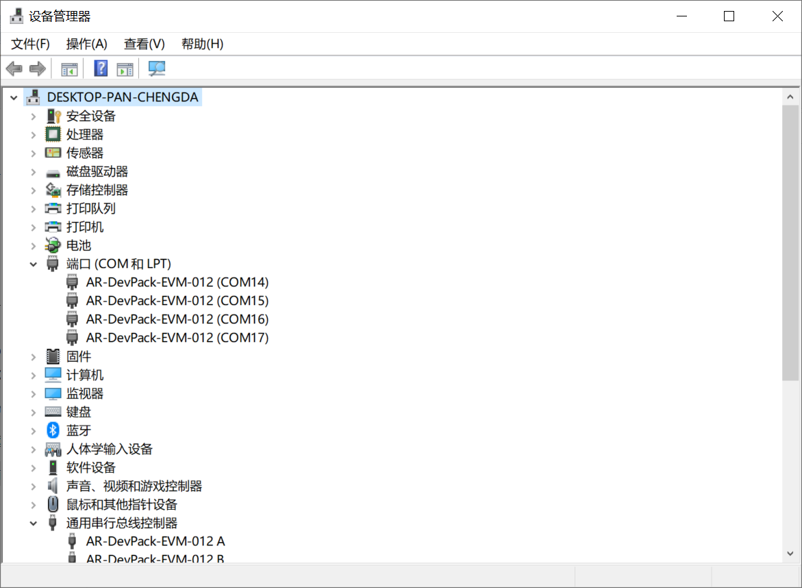
A USB line and A network line is connect between PC and DCA1000

3.
I do as below
3.1 Power ON
3.2 Run mmWave Studio 2.1.1.0
3.3 Run DataCaptureDemo_xWR.test.lua
3.4 watch output

4.

snapshot

4.1

4.2

4.3

6.

DataCaptureDemo_xWR.test.lua

--BSS and MSS firmware download
info = debug.getinfo(1,'S');
file_path = (info.source);
file_path = string.gsub(file_path, "@","");
file_path = string.gsub(file_path, "DataCaptureDemo_xWR.test.lua","");
fw_path = file_path.."..\\..\\rf_eval_firmware"

--Export bit operation file
bitopfile = file_path.."\\".."bitoperations.lua"

dofile(bitopfile)

partId = 6843

--ADC_Data file path
data_path = file_path.."..\\PostProc"
adc_data_path = data_path.."\\adc_data.bin"

-- select Device type
if (ar1.SelectCaptureDevice("DCA1000") == 0) then
WriteToLog("SelectCaptureDevice Success\n", "green")
else
WriteToLog("SelectCaptureDevice failure\n", "red")
end


--DATA CAPTURE CARD API
if (ar1.CaptureCardConfig_EthInit("192.168.33.30", "192.168.33.180", "12:34:56:78:90:12", 4096, 4098) == 0) then
WriteToLog("CaptureCardConfig_EthInit Success\n", "green")
else
WriteToLog("CaptureCardConfig_EthInit failure\n", "red")
end


--[[

WriteToLog("CaptureCardConfig_Mode Success001a\n", "green")
--AWR12xx or xWR14xx-1, xWR16xx or xWR18xx or xWR68xx- 2 (second parameter indicates the device type)
if ((partId == 1642) or (partId == 1843) or (partId == 6843)) then
if (ar1.CaptureCardConfig_Mode(1, 2, 1, 2, 3, 30) == 0) then
WriteToLog("CaptureCardConfig_Mode Success001b\n", "green")
else
WriteToLog("CaptureCardConfig_Mode failure\n", "red")
end
elseif ((partId == 1243) or (partId == 1443)) then
if (ar1.CaptureCardConfig_Mode(1, 1, 1, 2, 3, 30) == 0) then
WriteToLog("CaptureCardConfig_Mode Success\n", "green")
else
WriteToLog("CaptureCardConfig_Mode failure\n", "red")
end
end

if (ar1.CaptureCardConfig_PacketDelay(25) == 0) then
WriteToLog("CaptureCardConfig_PacketDelay Success\n", "green")
else
WriteToLog("CaptureCardConfig_PacketDelay failure\n", "red")
end

--Start Record ADC data
ar1.CaptureCardConfig_StartRecord(adc_data_path, 1)
RSTD.Sleep(1000)

--Trigger frame
ar1.StartFrame()
RSTD.Sleep(5000)

--Post process the Capture RAW ADC data
ar1.StartMatlabPostProc(adc_data_path)
WriteToLog("Please wait for a few seconds for matlab post processing .....!!!! \n", "green")
RSTD.Sleep(10000)


--]]

  • 1. The picture seems show incorrect before,

    2. I add as attachement again

  • 1. Network is set correctly ,and firware are closed .

  • 1. the USB cabe seem correct

  • 1.And DCA1000 is

    SW_CONFIG

  • 1.

    DCA1000 switch details 

  • I found a SOP mode on IWR6843 issue, let me check first.

  • Please read through the DCA1000 debug notes at:

    https://e2e.ti.com/support/sensors/f/1023/t/872161

    Best,

    Zigang


  • 1.
    1.1
    Now I need to support IWR6843 with LVDS function.

    1.2
    The IWR6843 board is not IWR6843ISK EVM + MMWAVEBOOST + DCA1000

    It is a similar customer IWR6843 board(designed refer IWR6843ISK)+ DCA1000

    1.3
    I add LVDS function follow C:\ti\mmwave_sdk_03_03_00_03\packages\ti\demo\xwr68xx\mmw\mss

    1.4
    does my IWR6843 board(firmware support LVDS) should start with SOP 011 (debug mode)?
    OR it can boot on function Mode?

    (I know IWR6843ISK+BOOST+DCA1000, mmwave_studio_02_01_01_00 guider , SOP 011 is used)


    2.
    What is details information on
    SOP[2:0] 011 development mode?

    (it is called debug mode also)

    I can found little information on SOP 011 Mode

    3.
    3.1
    Below is the copy info.
    [<< swra627.IWR6843BootloaderFlow.pdf>> ]

    From this point onward, the IWR6843 bootloader can operate in two modes: flashing and execution
    The bootloader checks the state of the sense on power (SOP) I/Os – SOP lines driven externally for
    choosing the specific mode (see Table 1).
    Table 1. SOP Lines and Boot Modes

    SOP2 (P9) SOP1 (G13) SOP0 (N13) Bootloader Mode and Operation

    0 0 1 Functional mode
    The device bootloader loads the user application from the QSPI serial flash to the
    internal RAM and switches the control to it.

    1 0 1 Flashing mode
    The device bootloader spins in loop to allow flashing of the user application (or the
    device firmware patch – supplied by TI).

    0 1 1 Debug mode
    The bootloader is bypassed and the R4F processor is halted. This lets the user
    connect the emulator at a known point.


    [ <<swru546c.MMWAVEICBOOST.pdf>> ]
    2.8.1

    The mmWave sensor device can be set to operate in three different modes based on the state of the SOP
    lines. These lines are sensed only during boot up of the mmWave sensor device. The state of the device
    is detailed by Table 9. A closed jumper refers to a 1, and an open jumper refers to a 0 state of the SOP signal going to the
    mmWave sensor device.

    Table 9. SOP Jumper Information


    SOP[2:0] 011 (SOP mode 2) = development mode

    SOP[2:0] 001 (SOP mode 4) = function mode

    SOP[2:0] 101 (SOP mode 5) = flash programming

    3.2
    On Above in <<IWR6843BootloaderFlow.pdf>
    It says

    0 1 1 Debug mode
    The bootloader is bypassed and the R4F processor is halted. This lets the user
    connect the emulator at a known point.

    When IWR6843 power on(SOP 011 on Debug mode), does the R4F processor is halted?
    And "This lets the user connect the emulator at a known point."? what is it means?

  • 1.
    On mmwave studio
    1.1
    C:\ti\mmwave_studio_02_01_01_00\mmWaveStudio\Scripts\DataCaptureDemo_xWR.lua
    It use firmware as below:

    C:\ti\mmwave_studio_02_01_01_00\rf_eval_firmware

    Are there the relative source code on it(IWR6843), I think it is helpful.(I need to write code on support LVDS)

  • HI, 

    OK, so you have a customer board.  And you added the LVDS streaming on your binary.   But for the raw data capture, we always recommend to use radar studio.  Is there change on your board that prevent you from using radar studio for data capture?

    Best,

    Zigang

  • I have blow questions, could you please replay? My customer board is refer to IWR6843ISK, I am not very sure on the little difference. But could you please replay me the below questions, they are basic question for me, I am not sure about them. 


    1.
    1.1
    Now I need to support IWR6843 with LVDS function.

    1.2
    The IWR6843 board is not IWR6843ISK + MMWAVEICBOOST + DCA1000EVM

    It is a similar customer IWR6843 board(designed refer IWR6843ISK)+ DCA1000

    1.3
    I add LVDS function follow C:\ti\mmwave_sdk_03_03_00_03\packages\ti\demo\xwr68xx\mmw\mss

    1.4
    does my IWR6843 board(firmware support LVDS) should start with SOP 011 (debug mode)?
    OR it can boot on function Mode?

    (I know IWR6843ISK+BOOST+DCA1000, mmwave_studio_02_01_01_00 guider , SOP 011 is used)


    2.
    What is details information on
    SOP[2:0] 011 development mode?

    (it is called debug mode also)

    I can found little information on SOP 011 Mode

    3.
    3.1
    Below is the copy info.
    [<< swra627.IWR6843BootloaderFlow.pdf>> ]

    From this point onward, the IWR6843 bootloader can operate in two modes: flashing and execution
    The bootloader checks the state of the sense on power (SOP) I/Os – SOP lines driven externally for
    choosing the specific mode (see Table 1).
    Table 1. SOP Lines and Boot Modes

    SOP2 (P9) SOP1 (G13) SOP0 (N13) Bootloader Mode and Operation

    0 0 1 Functional mode
    The device bootloader loads the user application from the QSPI serial flash to the
    internal RAM and switches the control to it.

    1 0 1 Flashing mode
    The device bootloader spins in loop to allow flashing of the user application (or the
    device firmware patch – supplied by TI).

    0 1 1 Debug mode
    The bootloader is bypassed and the R4F processor is halted. This lets the user
    connect the emulator at a known point.


    [ <<swru546c.MMWAVEICBOOST.pdf>> ]
    2.8.1

    The mmWave sensor device can be set to operate in three different modes based on the state of the SOP
    lines. These lines are sensed only during boot up of the mmWave sensor device. The state of the device
    is detailed by Table 9. A closed jumper refers to a 1, and an open jumper refers to a 0 state of the SOP signal going to the
    mmWave sensor device.

    Table 9. SOP Jumper Information


    SOP[2:0] 011 (SOP mode 2) = development mode

    SOP[2:0] 001 (SOP mode 4) = function mode

    SOP[2:0] 101 (SOP mode 5) = flash programming

    3.2
    On Above in <<IWR6843BootloaderFlow.pdf>
    It says

    0 1 1 Debug mode
    The bootloader is bypassed and the R4F processor is halted. This lets the user
    connect the emulator at a known point.

    When IWR6843 power on(SOP 011 on Debug mode), does the R4F processor is halted?
    And "This lets the user connect the emulator at a known point."? what is it means?

    4.
    On mmwave studio
    4.1
    C:\ti\mmwave_studio_02_01_01_00\mmWaveStudio\Scripts\DataCaptureDemo_xWR.lua
    It use firmware as below:

    C:\ti\mmwave_studio_02_01_01_00\rf_eval_firmware

    Are there the relative source code on it(IWR6843), I think it is helpful.(I need to write code on support LVDS)

  • Hi, 

    You will have to learn to follow the documentation and narrow down your question.  Please go through the steps to use radar studio to do data capture, and let me know where you stuck.    You can send the radar studio screen capture or log when you get stuck. 

    Here is training video that may be helpful.  This video is also listed in the debug notes I send you.  You can also try to follow all other document mentioned in that debug notes. 

    training.ti.com/dca1000-training-video

    Best,

    Zigang