This thread has been locked.

If you have a related question, please click the "Ask a related question" button in the top right corner. The newly created question will be automatically linked to this question.

OPT3101EVM: Calibration step 4: Phase offset ambient coefficients

Part Number: OPT3101EVM
Other Parts Discussed in Thread: OPT3101, OPT3101-SDK

Hi, 

I am using the OPT3101 EVM. Due to the specifications of the project I am working on, I have replaced the infrared LED for a green LED. I have also replaced the original photo diode and now I am using the SFH 213 photo diode.

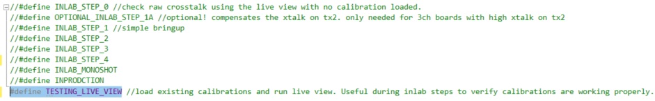
In order to calibrate the EVM using Visual Studio, I am following the OPT3101-SDK documentation. When I reach the step 4, the documentation says that it is recommended to measure the phase offset with an amplitude over 10000 codes. I configured the illumination current at 70 mA and the Max Ambient Current at 20 uA. I am using a reflective tape on the target which is 80 mm from the EVM. When I run the step 4, the amplitude measured is 50 codes, while running the TEST step, the amplitude is 12000 codes. Could you please tell me how can I reach the 12000 codes running the step 4? Moreover, why am I getting different amplitude values for the same conditions?

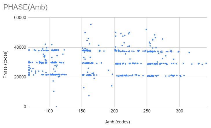
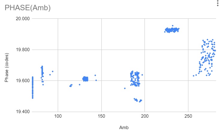
In addition, I went on with this calibration step although the 10000 codes were not reached. The plot obtained is the following one.

Could you tell me why am I receiving this 3 slopes?

Thank you,

Olga

  • Hi Olga,

    I don't think your picture attached properly. Could you please repost this? Also could you elaborate what you mean by test step when you say "while running the TEST step, the amplitude is 12000 codes".  Could you also provide more details for this step "When I run the step 4, the amplitude measured is 50 codes"? What exactly are you running and if you could share the output for this that would be helpful.

    Best,

    Alex

  • Hi Alex

    Thank you for your quick reply.

    Here is the reposted picture.

    Alex Bhandari-Young said:
    Also could you elaborate what you mean by test step when you say "while running the TEST step, the amplitude is 12000 codes".

    I am running the SDK in Visual Studio. I'm following the docs "OPT3101 SDK Users Guide" and the "How to set up and calibrate OPT3101 based systems for

    proximity sensing". The different steps for calibration are defined in the main.cpp. The TESTING_LIVE_VIEW is used for verifying that the calibration works properly.

    When I run it, I get an amplitude of around 11000~12000 codes.

    Alex Bhandari-Young said:
    Could you also provide more details for this step "When I run the step 4, the amplitude measured is 50 codes"? What exactly are you running and if you could share the output for this that would be helpful.

    When I run the INLAB_STEP_4 of the SDK for getting the phase ambient coefficients, the amplitude measured is around 50 codes for the exact same setup (distance to target, same target and same LED current).

  • Hi Alex, 

    I have tried to get higher amplitude codes (16000-24000) running the INLAB_STEP_4 by changing the retro reflective tape on the target, choosing another lamp and changing the distance from the target, but nothing worked. I finally managed how to get higher amplitude codes by changing a line of the SDK code. I observed in the code that when going through all the valid TX channel and register set configurations, the channel was forced to be TX1. I attach below the part of the code I am referring to (function: calibrationSession_perDesignCalibrationPhaseAmbient from the OPT3101_Calibration.cpp file):

    for (c0 = 0; c0 < 3; c0++) { ///* Loops though all the valid TX channel and register set configurations

    if (this->configurationFlags_isTXChannelActive[c0]) { // Checking is TX channel is active for this profile

    for (c1 = 0; c1 < 2; c1++) { // Loop to iterate over the H/L registers

    c1 = 0;

    c0 = 1;

    Nevertheless, all the previous calibration steps are only using the TX0 to perform the measurements and collect data. Moreover, the channel where the LED is soldered is TX0. I have only removed the line in the code where the c0 variable is set to be 1 in order not to force the TX1 to be chosen, and I ran the step again. After this modification, I started getting the expected results from the beginning.

    The amplitude code is now between 16000 and 24000 codes. 

    Moreover, when I plot the data collected I am not getting those three slopes I attached in the last post. The plot obtained now is the following one:

    Could you please verify if what I have done is correct?

    Thank you,

    Olga

  • Hi Olga,

    Have you used the configurator tool to generate a configuration file for the SDK? If the device is looping through TX1 and Tx2 when you only have one LED on tx0 this would mostly likely be an incorrect config file as this sets the loop ranges.

    Regarding "all the previous calibration steps are only using the TX0 to perform the measurements and collect data" phase ambient can be done at a single setting but all other calibration need to be done for all current settings. 

    In the text you mention running phase offset - is that problem resolved? Because in your latest post I just see questions about the phase ambient.

    Regarding phase ambient, please first ensure that all other calibration tests were done correctly (temp xtalk, xtalk correct, phase temp) and that the board is stable over temperature. What is the raw xtalk magnitude measured before correction? Then we can look at your test setup for phase ambient. Can you share a picture of the setup and describe how you are varying the light level? Why are there large gaps in the ambient in the graph where it jumps 130 to 190 to 230? Also there are also locations where there are many phase values for a given ambient in your plot. It looks like the readings are not stable when ambient is constant. If you refer to the guide you see that plot data is much more stable so this will need to be troubleshooted.

    Best,

    Alex