This thread has been locked.

If you have a related question, please click the "Ask a related question" button in the top right corner. The newly created question will be automatically linked to this question.

LMP91000: Oxygen measurement with the LMP 91000

Part Number: LMP91000
Other Parts Discussed in Thread: REF2933

Hi everyone,

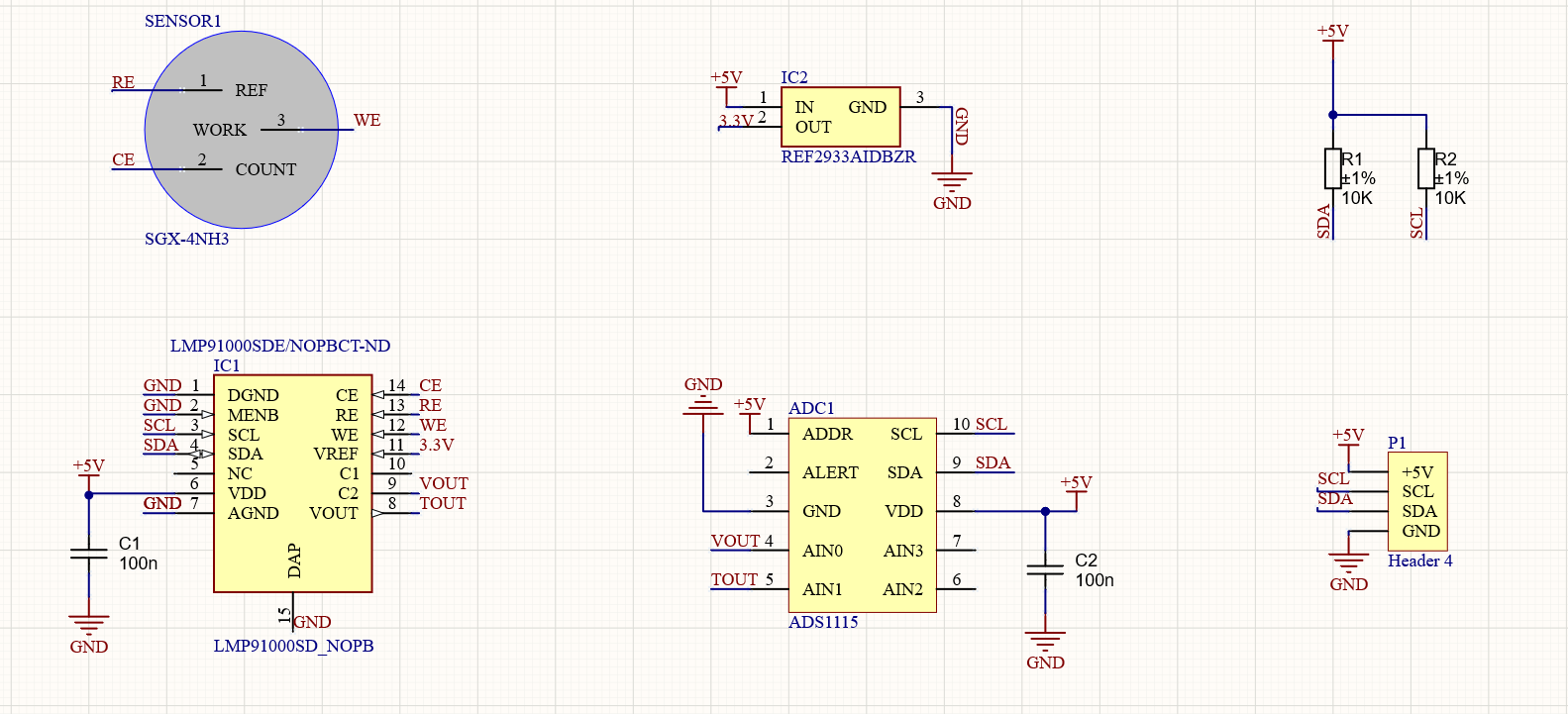
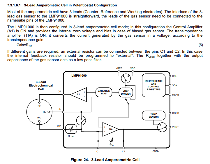
I´m suffering some problems with the use of the LMP91000 for measuring oxygen.

The problem comes due to the change in the supply since the output value changes when I change the supply.

When the circuit is supplied via USB connected through the PC , output values are around 95 microAmps. However, when it is supplied via an USB which is connected to an external battery the output values are around 108 microAmps.

Best regards.

  • Dear Esteban - 

    Please post or attach your schematic, which will be very useful in assisting you further with constructive feedback. 

  • Dear Josh,

    I attach the schematic.

  • Esteban,

      My experience is that the USB 5V from a computer is typically an LDO and using a USB from a battery is typically a switching boost regulator running off of a single Lithium cell. This means that the switching noise from a boost circuit can effect the REF2933 output voltage due to high frequency noise.

    It's possible that you are seeing a VREF shift. Add a 0.47uf capacitor to the input of the REF2933 and a 100nF capacitor to the output of the REF2933. This should stabilize the noise that is causing the VREF shift.

  • Thanks for your answer Gordon,

    We have added both capacitors as you said but they had no impact. The signal is still way bigger when the supply comes from the external battery.

    Any other idea?

  • Esteban,

      Have you measured the VREF voltage on each supply. I would be interested to know if the VREF is moving. The VREF is the bases for accuracy for this IC.

    1) connect to PC, measure the VCC and VREF

    2) connect to battery, measure the VCC and VREF

    Please let me know the voltages for each that you are measuring.

    The change you are seeing is 13uA, that means about 13% change since you are near 100uA. That is a lot of change. The VREF you selected is +/-2%. Based on what you report we need to determine if the change in VREF will change your current 13uA. It's possible that you need a 1% or even a 0.5% VREF.


  • Hi Gordon,

    Here are the values I've measured in both cases:

    1) Connected to PC: VREF = 3.2910, VCC= 4.794V

    2) Connected to battery: VREF = 3.2913V, VCC = 4.960V

  • Esteban,

      Check your register settings. you should be running external reference set for VREF. The REF2933 looks like it's doing a good job. I wasn't expecting such a large change in VCC.  I will look at the VCC voltage on the bench and see if having the VCC change by this amount will effect the measurement value. I didn't think that it would, but I will check anyway.

  • Hi Gordon,

    I've been using the LMP91000 library for programmig the device. Everything looks ok for me but anyway I will paste the code here so you can check it.

    LMP configuration part of the firmware:

    LMP.standby();
    LMP.enable();
    LMP.unlock();  // Enables changing the register
    LMP.setMode(5); // 3 lead mode
    LMP.setExtRefSource(); // External voltage reference
    LMP.setRLoad(3); // Rload, 100 Ohm
    LMP.setGain(3); // Rtia 14K Ohm
    LMP.setBias(10, 0); //Bias a -600mV, 10 = 18%, 0 = negative
    LMP.setIntZ(3); // Bypass = 3.3V (external ref)

    On the other hand, I will also make some tests with other voltage values to supply my microcontroller with an DC power supply and I will send you the results.

    Best regards, 

    Asier.

  • Esteban - 

    it just occurred to me that you did not connect CE and RE together - with all other three terminal O2 sensors this is what is done. 

  • Hi Josh,

    Thanks for your contribution. I don't really think that is the problem since the configuration I want to use is the 3 lead mode,in which every lead is connected separately as you can see in the picture below.

    Best regards.

  • Hi Gordon,

    As I told I've been doing some tests with the DC supplier and as you suspected the change in the Vcc has direct influence in the value of the output singal. Here are some examples:

    Vcc = 4.895 V  Output = 109.87 uA

    Vcc = 4.933 V Output = 112.91 uA

    Vcc = 4.945 V Output = 113.5 uA

    Vcc = 4.955 V Output = 113.59 uA

    Vcc = 4.975 V Output = 114.8 uA

    Which could be the reason?

    Best regards,

    Asier.

  • Esteban - 

    Actually - that is an Ammonia sensor, not an Oxygen sensor - so you may either change sensors or set up the LMP91000 similar (and you are right there, with those sensors, you have a three terminal arrangement) 

    with a similar sensor from City Tech, NH3 3E 10 SE (from the sensor database in the LMP91000 GUI), the load was set for 10 Ohms and the RTIA was set for 120k, with the Vref divider set for 20%. 

  • Hello Josh,

    The sensor in the schematic is not the same we are using, we are using the S+4OXLF oxygen sensor by DD Scientific. I used the one on the eschematic due to its' footprint is the same as S+4OXLF ones. Sorry if that has confused you.

    Thank you,

    Best regards.

  • Esteban,

      The data you provide definitely show a sensitivity to the VCC. Can you read back the data registers to verify that the systems is using the VREF. I know this sounds redundant, but we need to know that the code you are using is setting the part up correctly.

    It should not change the current with VCC.

  • Gordon,

    I'm pretty sure that my register is well configured. As I told you before, I'm using the LM91000 library, https://github.com/LinnesLab/LMP91000, and for configuring the reference source as external I use the command setExtReFSource().

    //void LMP91000::setExtRefSource() const
    //
    //Unlocks the REFCN register for "write" mode. First reads the register to
    //ensure that the other bits are not affected. Writes a "1" to the 7th bit of
    //the REFCN register.
    //
    //Sets the reference source of the LMP91000 to an external reference provided at
    //the Vref pin.
    //
    //Please consult page 22, "Section 7.6.4 REFCN -- Reference Control Register
    //(Address 0x11)" of the datasheet for more information.
    void LMP91000::setExtRefSource() const
    {
    unlock(); //unlocks the REFCN register for "write" mode
    uint8_t data = read(LMP91000_REFCN_REG);
    data |= (1 << 7); //writes a "1" to the 7th bit
    write(LMP91000_REFCN_REG, data);

  • Esteban,

    The data sheet shows that the PSRR and the output vs VDD has little to no impact on the measurement. I know that you feel comfortable with the code going into the device, but you really need to read the registers back to verify that it really is using external reference. I have not seen this except when the device has not been configured properly. Once you verify the registers are correct, then we can look else where.

  • Hi Gordon,

    The data you have sent referes to the output of the temperature sensor instead of the oxygen sensor, my problem comes due to the change in the output value of the oxygen sensor. However, I understand the signal of the sensor shouldn't neither change with the change of VCC.

    Regarding registers, I have been doing some test changing between external and internal reference source and also changing the % of them and everythig seems to be perfect so we might discard that option. 

    Best regards,

    Asier.

  • Asier,

      Because you have a large variation in VDD and we can't identify what is causing the current to shift. My recommendation is to run the LMP91000 VDD directly from the REF2933 and set the VREF to VDD. Then it wont matter what the USB voltage will be.

    The REF2933 can supply 25mA and the average input current to the LMP91000 is 10uA. Make sure that you have the proper capacitance to supply inrush current to the LMP91000 and you will be good to go.

  • Hello Gordon,

    I have been doing some test changing the values of IntZ, Rtia and Rload.

    When IntZ = 3.3V (Vref), Rload = 100R and Rtia = 3500R, the output voltage is 4.6426V , which is higher than IntZ. In that case, the output current of the sensor must be negative following the equation Voutput = IntZ- (Rtia * Iwe). Furthermore, I have seen that the output voltage was limitited by the supply voltage of my circuit, in other words, the output voltage is always near the supply voltage (+/- 4.8V).

    However, with other IntZ values the circuit works different. When IntZ = 0.658 (20% Vref), Rload = 100R and Rtia = 7000R, the output voltage is 0.03487V , which is lower than IntZ. This means that the current is positive following the equation aforementioned. When IntZ = 1.647 (50% Vref), Rload = 100R and Rtia = 7000R, the output voltage is 0.04144V. 

    Hope you can give some light,

    Best regards,

    Asier.

  • Asier,

      The sensor you have selected will probably never read zero, because there will always be Oxygen, unless you can produce a vacuum to remove it.

    That means that you will never read Vref as your value. It looks like you are near maximum which tells me that you need to adjust your current range. Set Rload to 10 Ohms and increase TIA gain to get the correct response fro the sensor.

    This part has a trans-impedance amplifier inside so it is converting current to voltage. The Rload is some what of a current shunt. So if the voltage is to high then lower the range by setting the shunt lower to get a lower voltage drop, then set the gain to get a proper scale.

  • Hi Josh,

    I've been using the LMP91000 software trying to find the correct values for IntZero, Rload and Rtia introducing the different specifications of my sensor. Once I entered the values the software told me to short the RE and CE to properly configure it for Oxygen type sensors. So my question is if with every oxygen sensor this must be done or not, and if not in which cases this should be done. I'm also attaching the datasheet of the sensor so you can check the different parameters.

    Best regards,

    Asier.

    s_4oxlf_datasheet_iss2.pdf

  • Asier,

    The manufacture of the O2 sensor that you are using recommends a 2 wire configuration. They also show an Rload of 100Ohms. On their web site under support their are a few documents on this.

  • Thanks for your reply Gordon,

    I saw that circuitry some time ago. However, that circuitry doesn't apply any bias on the sensor which in essential for the right performance of it. The company advises to use this circuitry for S+4OXLF but the functioning of it is very different since it doesent use any TIA. The output is measured through the 100R resistor in the potentiostat part of the circuit.

    Best regards,

    Asier.

  • Asier.,

    My experience with O2 sensors are that they are operated in 2 wire mode.

    It may be a good idea to contact the manufacture of the sensor and have then guide you in the use of this sensor. They should have a good idea of how to set the variables and wire the sensor to get the results that you are looking for.

    I can only guess what this sensor really needs. Let me know if I can help with the LMP91000.

  • Hi Gordon,

    After following your advices and doing several tests it seems I have finally found the correct configuration for the LMP91000:

    Rload = 100 R

    Rtia = 2750 R

    IntZ = 1.649 (50% VREF)

    Regarding the operation mode, I kept it in the 3 lead mode.

    By the moment everything looks good and it is time to test its accuracy.

    Thank you for all your help,

    Best regards,

    Asier.