This thread has been locked.

If you have a related question, please click the "Ask a related question" button in the top right corner. The newly created question will be automatically linked to this question.

IWR6843: Antenna pcb question

Part Number: IWR6843

Hello!

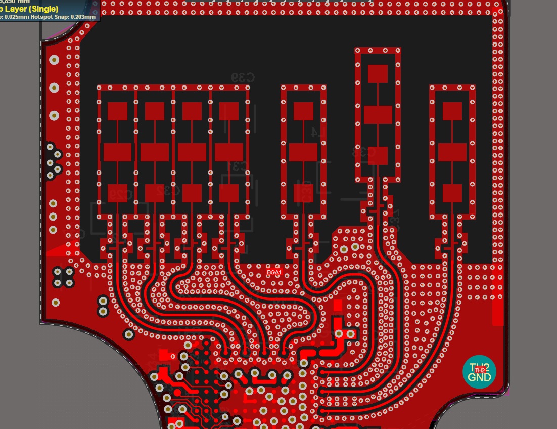
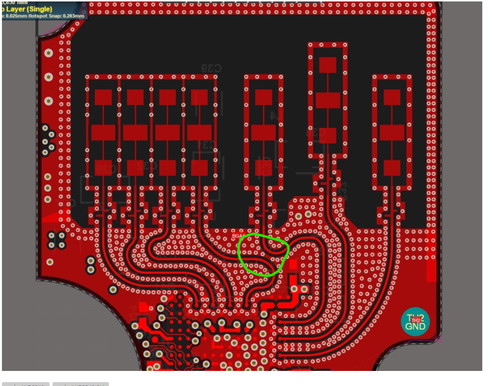
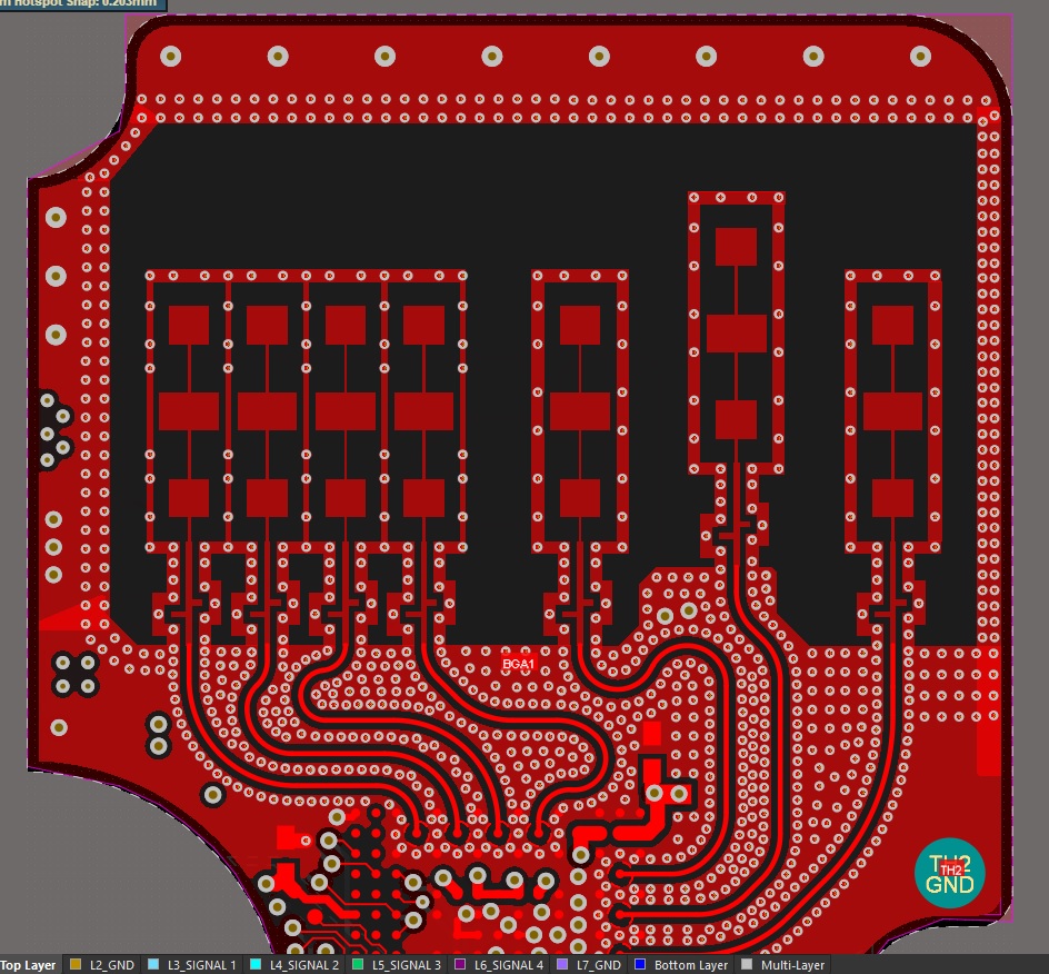
We design our custom board based on IWR6843ISK board design.  We changed the position of the IWR6843 chip. The length of the traces is matched and  the rest of the parameters are close to those used in IWR6843ISK reference design. Could you tell me please if  the tracks to RX antennas in such way is ok? Trace RX4 is especially interesting, can it cause problems because of its shape?

  • Hello AndreyB,

        It's hard to comment by just looking at the top layer alone, We may have to look at the complete design. Also have you done any Antenna simulations? 

    By looking at the RF routing, it appears there could be a coupling problem shown below. RX1 to TX4 are very close this would without dense mico via, this should be avoided.

    Thanks and regards,

    CHETHAN KUMAR Y.B.   

  • Hello, CHETHAN!

    I've tryed to move the TX1 track a little bit farther and add some vias between RX4 and TX1 tracks. Is that helps or we need more space?

    Our antenna has the same parameters as TI IWR6843ISK reference design: material, traces width, air gap, layer stack. I can share the project with you if needed.

    We haven't done the simulation. As I understand we need HFSS tool for that? Maybe you have some guides how to do the simulation in it from altium?

  • Hi,

    You need HFSS for the simulation, we provide the altium design file and you can import that into HFSS for your simulation.

    To improve the TX-RX isolation, you may want to increase the space and add more ground vias.

    Regards,

    Charles O