This thread has been locked.

If you have a related question, please click the "Ask a related question" button in the top right corner. The newly created question will be automatically linked to this question.

PGA460: Inserting the sensing volume

Part Number: PGA460

Hi,

I like to put a veriable resistor between transducer and PGA460 INN for fine adjustment by hand.
It is needed for covering tansducer's gain variation.
Although it needs internal impedance and gain balance info of PGA460.

As much as I see the recommended value in PGA460-Q1 doc page 107,
it tells Rinp is 3k ohm.
So it is supposed that 5k ohm variable resistor is suitable since it will make 2.5k ohm center resistance that is close to the recommendation.

Is all above suitable for sensing fine tune by hand for PGA460?

Best Regards,
Andy

  • Hi Andy,

    I'm not entirely clear where you have placed the variable resistor. A resistor should not be placed between the transducer positive terminal and the INN pin; this may damage the device. The only resistors around the transducer network should be the required series R_INP resistor (typically 0.1 to 3 kOhms) and an optional damping resistor between the transducer's positive terminal and ground.

    What is meant by transducer grain variation? Are you referring to the characteristic changes over temperature. The goal of the internal time varying gain amplifier is that you can compensate for the gain variation in software (by adjusting the time varying gain values as a function of temperature and/or other conditions).

    Please provide a schematic and a result screen capture of the changes you have made for me to review.

  • HI Akeem,
    Sorry, I noticed last night that I did not indicate the exact place where I put the variable resistor.
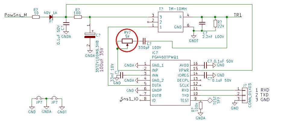
    Here's my schematic and the red circle is the variable resistor. TR1 is the positive terminal of transducer.

    I meant transducer gain variation as the transducer production quality deviation. Some of them gets the bounce echo stronger than average. Some of them gets weaker.
    It needs to be adjusted by user at the using place.

    It seems my schematic needs 100 ohm between VR and INP according to your explanation of R_INP resistor (typically 0.1 to 3 kOhms).
    100 ohm resistor protects PGS460 INP port from the high voltage damage. Is that what you meant as damage to the device?

  • Hi Andy,

    Thank you for clarifying the position of your variable resistor. There is no concern for device damage in this position.

    The R_INP has two purposes:

    1) To improve radiated immunity. In systems where the PGA460 module is exposed to harsh levels of radiated emissions, the value of R_INP is typically higher (for example, 3kOhm). In applications where the PGA460 module is in a controlled environment, the value of R_INP can be much lower (for example. 0.1kOhm). It is important to note as the value of R_INP increases, the receiver sensitivity decreases, so you do not want to place too large of a value; otherwise, you can cause major attenuation to the return echo signal (preventing proper detection).

    2) To reduce overall current into the INP pin. Note, the value of C_INP and C_INN are more crucial to limiting current and protecting the INP pin, but the R_INP component can offer additional protection.

    Reiterating my previous suggestions: instead of using a variable resistor to compensate for the sensitivity differences between transducers, just shift the time varying gain (TVG) gain level register values of the PGA460. This would have a similar effect, such that for very sensitive transducers, you reduce the TVG levels, and for less sensitive transducers, you increase the TVG levels. Either way, using the TVG registers or an external variable resistor are both acceptable solutions, and there is no problem using either.